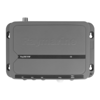
1.Checktheselectedlocationforthehandsetclip,aclearat
areaisrequired,withsufcientspacearoundittoplaceand
removethehandset.
2.Usingapencil,offerupthehandsetcliptothedesired
locationandmarkthelocationofthescrewholesonthe
mountingsurface.
3.Drillthemountingholesusingasuitablesizedrillbit.
4.Holdtheclipinplaceandsecureusingthescrewsprovided.
Note:Drillbit,tapsizeandtighteningtorqueisdependenton
thethicknessandtypeofmaterialtheunitistobemountedon.
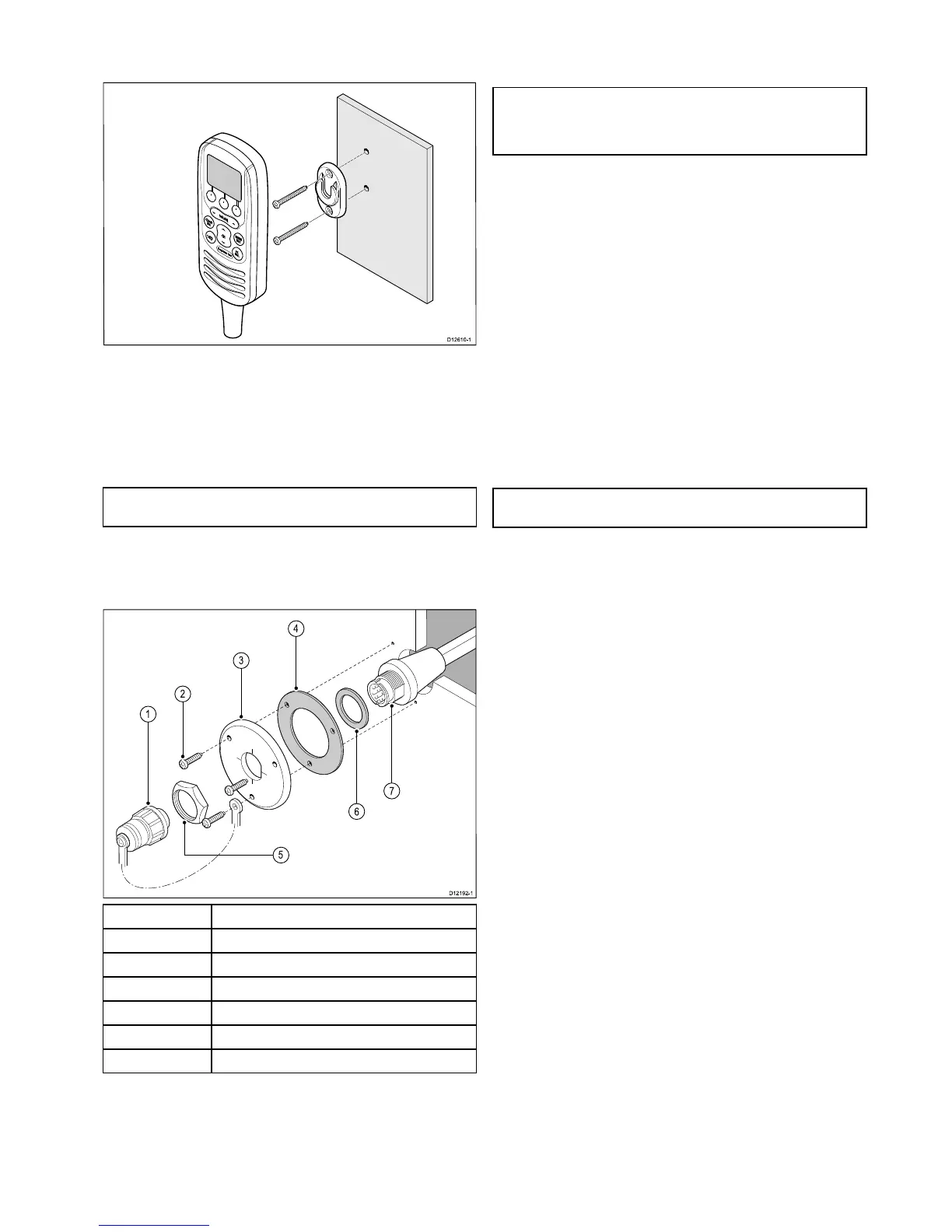
Pass-throughpanelplatemounting
Wheninstallingthehandsetusethesupplied,handsetextension
cablekittopassthecablethroughapanel(e.g.bulkhead).
1
Splash-proofcap
2Mountingscrewsx3
3Mountingplate
4
Gasket
5
Nut
6Washer
7
Extensioncableconnector
1.Checktheselectedlocationforthemountingofthehandset
cableextensionmountingplate,aclearatareaisrequired.
2.Usingapencil,offerupthemountingplatetothedesired
locationandmarkthelocationofthescrewholesandthe
centerholeonthemountingsurface.
3.Drillthemountingholesusingasuitablesizedrillbit.
4.Drillthecenterholeusinga25mm(1in.)holecuttingsaw.
5.Holdtheclipinplaceandsecureusingthescrewsprovided.
6.Pulltheconnectorendofthecablethroughtheholeinthe
mountingpanel.
Note:Thehandsetextensioncableincludesaspeakercable.
Ifyouarenotconnectinganexternalpassivespeakerthen
coverthespeakercablewithwaterprooftapeorsealantto
preventcorrosion.
7.Insertthewasher(labelled6inthediagrambelow)overthe
endoftheconnector.
8.Insertthegasket(labelled4inthediagramabove)overthe
endoftheconnector.
9.Insertthemountingplate(labelled3inthediagramabove)
overtheendoftheconnector,ensuringthatthescrewholes
arealignedwiththerespectiveholesinthegasketandthe
mountingpanel.
10.Placethenut(labelled5inthediagramabove)overthe
connectorandtightenclockwiseusinga13/16in.(21mm)
socketwrench.
11.Alignthesmallendofthesplash-proofcap(labelled1inthe
diagramabove)withoneofthescrewholesonthegasket.
12.Securethemountingplatetothemountingsurfaceusingthe
suppliedscrews.
13.Attachthehandsetormicrophonetothecableconnectorand
rotateclockwisetosecure.
14.Connecttheoppositeendofthecabletotherequired
connectoreitheronthebasestationortoanother
pass-throughpanelplateconnector.
Note:Drillbit,tapsizeandtighteningtorqueisdependenton
thethicknessandtypeofmaterialtheunitistobemountedon.
Locationandmounting
29
 Loading...