2.2Installationchecklist
Installationincludesthefollowingactivities:
InstallationTask
1Planyoursystem.
2
Obtainallrequiredequipmentandtools.
3
Siteallequipment.
4Routeallcables.
5
Drillcableandmountingholes.
6Makeallconnectionsintoequipment.
7
Secureallequipmentinplace.
8Poweronandtestthesystem.
Schematicdiagram
Aschematicdiagramisanessentialpartofplanning
anyinstallation.Itisalsousefulforanyfutureadditions
ormaintenanceofthesystem.Thediagramshould
include:
•Locationofallcomponents.
•Connectors,cabletypes,routesandlengths.
2.3Inboardautopilotsystem
Atypicalinboardautopilotwillconsistoftheitems
shown:
1.Autopilotcontrolhead—Thisprovidesthe
displayandcontrolsrequiredtousetheautopilot.
Multiplecontrollerscanbeaddedifrequired,for
exampleacontrollerateachhelmposition.
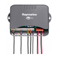
2.Coursecomputer—Thisisthecentralintelligence
huboftheautopilotsystem,linkingthecontrolhead
tothedriveunit.
3.Driveunit—Thedriveunitinterfaceswithyour
boat'ssteeringsystem.
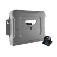
4.Fluxgatecompass—Theuxgatecompass
providestheautopilotwithamagneticheading
requiredformaintainingacourse.
5.Rudderreference—Requiredforsomesystems
only.Thisprovidesfeedbackfromtherudderand
canenhancesteeringperformance.
Note:Hydraulicdriveunitsshouldalwaysusea
rudderreferencetransducer.Ifinanydoubtplease
contactRaymarinecustomersupport.
Inadditiontheautopilotmayreceivedatafromother
components,forexample:
•Multifunctiondisplay—Theautopilotcanconnect
toacompatiblemultifunctiondisplay.Thisprovides
enhancedcapabilitiesforcreatingandfollowing
routes.
•GPS—Usuallyreceivedfromamultifunctiondisplay,
theautopilotusespositiondatawhenfollowingroutes
andcalculatingtheoptimumcoursetosteer.
•Windtransducer—Theautopilotcansteerrelative
toaspeciedwindangle.
Planningtheinstallation
11
 Loading...