Chapter 3, ST40 Bidata Instrument
ST40 Instruments Service Manual 83149-2 2-19
E22039
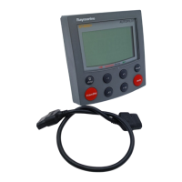
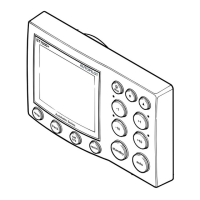
Chapter 3: ST40 Bidata Instrument
Input/output signals
Connections to instrument
D4810-2
DEPTH_0V (Screen)
DEPTH+ (Blue)
DEPTH- (Black)
BATT+ (Red)
BATT- (Screen)
STALK (Yellow)
SCREEN (Screen)
0VANA (Brown)
SPD (Green)
TEMP (White)
12V_SPD (Red)
Raymarine
Limited
Signal Description
STALK Intermittent streams of (nominal) 12 V pulses
BATT- 0 V
BATT+ Nominal 12 V dc supply
DEPTH- Intermittent pulses at 200 kHz, approximately 400 µs wide, 300 V peak-to-peak
DEPTH+ Intermittent pulses at 200 kHz, approximately 400 µs wide, 300 V peak-to-peak
DEPTH_0V 0 V
12V Approximately 11.2 V dc out
SPD With transducer attached, spinning paddle-wheel produces pulses
approximately 11.2 V in amplitude @ 5.5 Hz/Knot.
SCREEN 0 V
TEMP With transducer attached, voltage here is dependent on
temperature. Approximately 1.8 V at 0 degrees C.
OVANA 0 V
Refer also to the ST40 Bidata circuit diagram.
Self-test procedure
Each ST40 instrument has built-in self-test functions to aid fault diagnosis.
To self-test an ST40 Bidata instrument:
• Press the and keys simultaneously for 4 seconds, to access self-test mode,
then within 2 seconds, press the and keys together momentarily, to start
self-test stage 1.

 Loading...