ASCII Programming
MI3 Rev. G Nov/2015 119
18.5.3 Emissivity Setting and Alarm Set points
The device allows three choices for the emissivity setting and two for the alarm output setting.
ES Selection of the emissivity setting
ES=I Emissivity set by a constant number according to the „E“ command
ES=E Emissivity set by a voltage on FTC1 (analog input)
ES=D Emissivity set by the entries in a table (selected by digital inputs FTC1 – FTC3)
?CE asks for the emissivity value that is actually used for temperature calculation
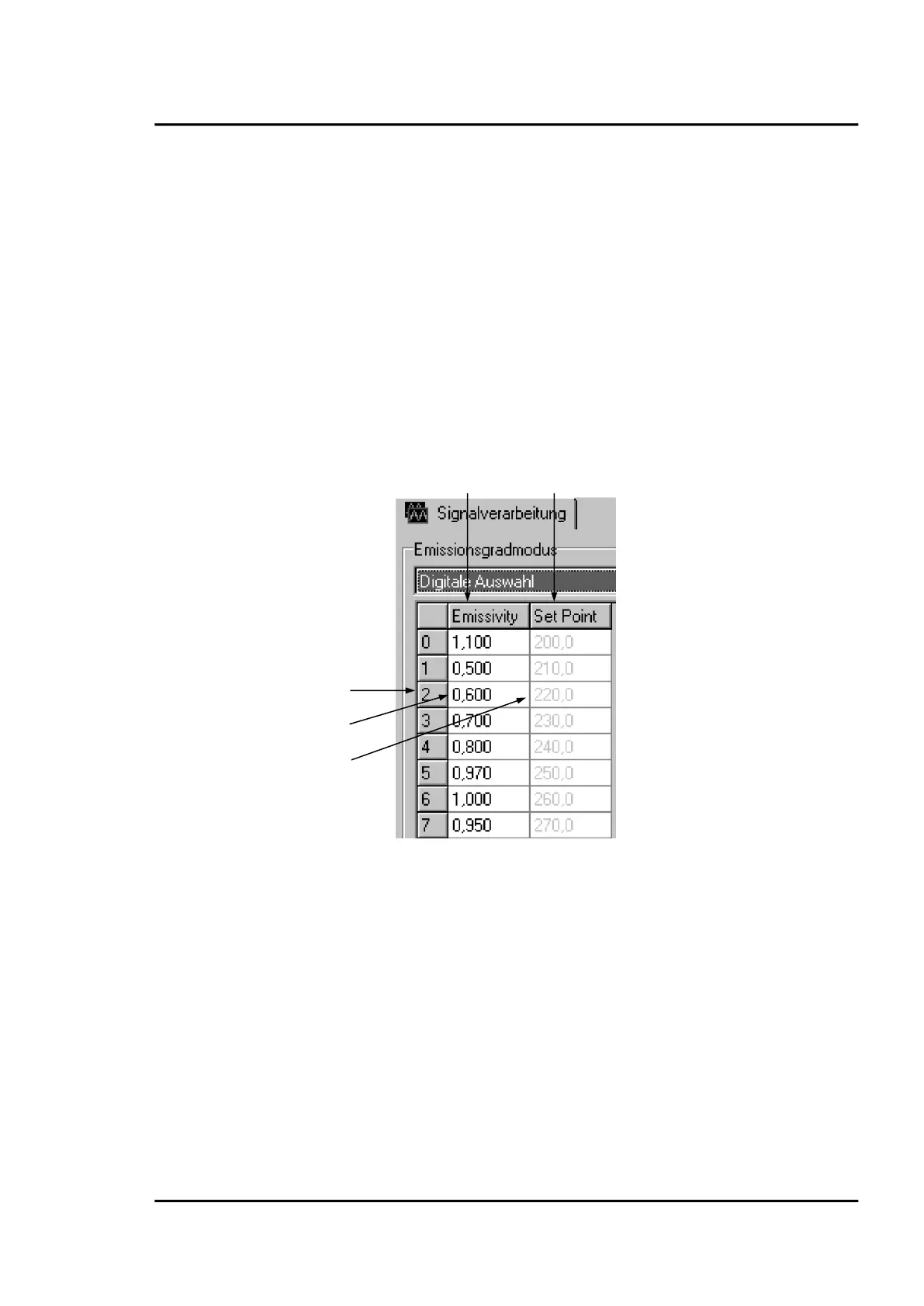
There are eight entries possible for emissivity setting ① and a related set point (threshold) ②. To be
able to write or read these values, use the following commands:
EP=2 set pointer for table entry, e.g. to line 2 ③
EV=0.600 set the emissivity value for line 2 to 0.600 ④
SV=220.0 set the set point (threshold) for line 2 to 220.0 ⑤
Figure 92: Table for Emissivity and Set Points
To activate these emissivity settings, you need to have the 3 external inputs (FTC) connected.
According to the digital combination on the FTC wires, one of the table entries will be activated, see
section 7.2 Emissivity (digital), page 44.
18.5.4 Post Processing
The following parameters can be set to determine the post processing mode. See section 8.5 Post
Processing, page 53.
P=5.0 peak hold, hold time: 5 s
F=12.5 valley hold, hold time: 12.5 s
G=10.0 averaging, average time (90%): 10 s
XY=3.0 advanced peak hold, hysteresis: 3 K
XY=-2.0 advanced valley hold, hysteresis: 2 K