Modbus
MI3 Rev. G Nov/2015 97
15 Modbus
The Modbus protocol follows the master/slave model. One master controls one or more slaves.
Typically, the master sends a request to a slave, which in turn sends a response. The request/response
mechanism is called a transaction. Requests and responses are also referred to as messages.
Specification:
Version: Modbus serial line (RS485)
Mode: RTU (Remote Terminal Unit)
Physical layer: RS485, 2 wire, electrically isolated
Baud rate: 9.6, 19.2, 38.4, 57.6, 115.2 kBit/s
Connection terminal
Address range: 1 to 247 (for the Modbus device)
Parity even
The detailed Modbus specification can be found under http://www.modbus.org/.
15.1 Wiring
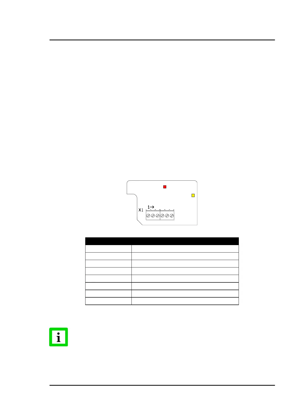
15.1.1 Comm Box (metal)
GND (output, used for external termination)
+ 5 V (output, used for external termination)
ON while communicating (ON for 2 s on initial power up)
Error (ON for 2 s on initial power up)
Figure 83: Modbus Terminal for Comm Box (metal)
The termination for Modbus networks must be realized externally by the user!