Inputs
44 Rev. G Nov/2015 MI3
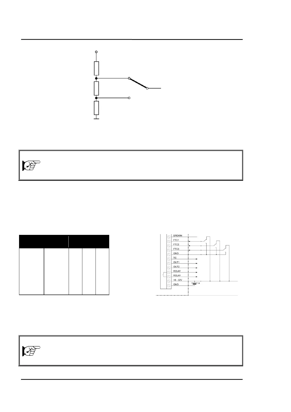
Figure 25: Adjustment of Emissivity at FTC Input (Example)
7.2 Emissivity (digital)
emissivity (digital control)
The box electronics contains a table with 8 pre-installed settings for emissivity. To activate these
emissivity settings, you need to have the inputs FTC1, FTC2, and FTC3 connected. According to the
voltage level on the FTC inputs, one of the table entries will be activated.
0 = Low signal (0 V)
1 = High signal (from 5 V to VDC)
A non-wired input is considered as not defined!
1.100
0.500
0.600
0.700
0.800
0.970
1.000
0.950
Figure 26: Digital Selection of Emissivity with FTC Inputs
The values in the table cannot be changed through the control panel.
7.3 Ambient Temperature Compensation
Ambient Temperature Compensation
To the FTC input
of the box