Inputs
MI3 Rev. G Nov/2015 43
7 Inputs
Three external inputs FTC1, FTC2, and FTC3 are used for the external control of the unit.
You cannot enable the input functions through the control panel!
Emissivity (analog control)
Emissivity (digital control)
Ambient Background Temperature Compensation
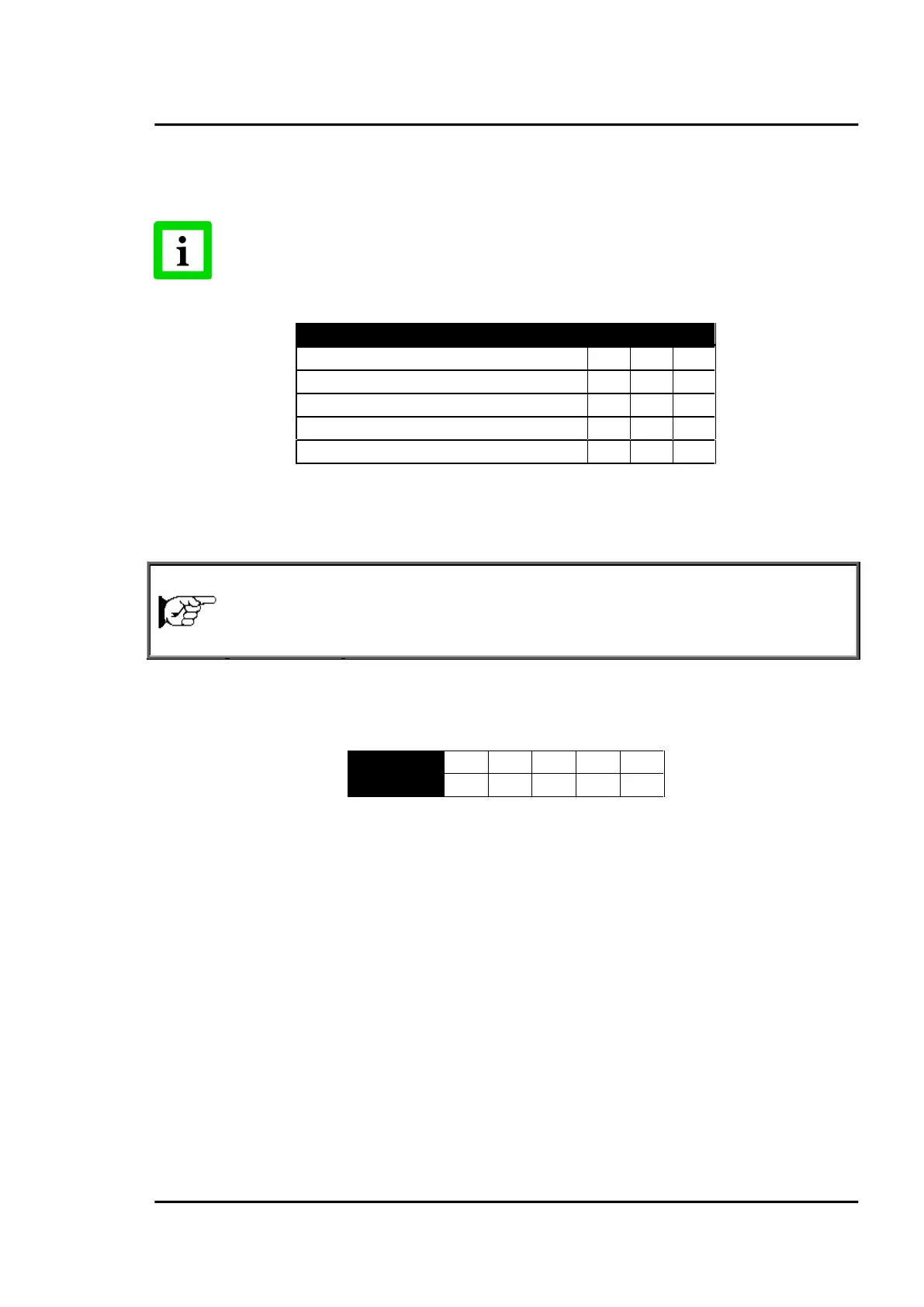
Table 2: Overview for FTC Inputs
7.1 Emissivity (analog)
emissivity (analog control)
The FTC1 input can be configured to accept an analog voltage signal (0 to 5 VDC) to provide real time
emissivity setting. Each input can support one head. The following table shows the relationship
between input voltage and emissivity:
Table 3: Ratio between Analog Input Voltage and Emissivity
Example:
This process requires setting the emissivity:
for product 1: 0.90
for product 2: 0.40
Following the example below, the operator needs only to switch to position “product 1” or “product
2”.