EasyManuals Logo

RayTek MI3 User Manual

RayTek MI3
146 pages
To Next Page IconTo Next Page
To Previous Page IconTo Previous Page
Page #90 background imageLoading...
Page #90 background image
Profibus
90 Rev. G Nov/2015 MI3
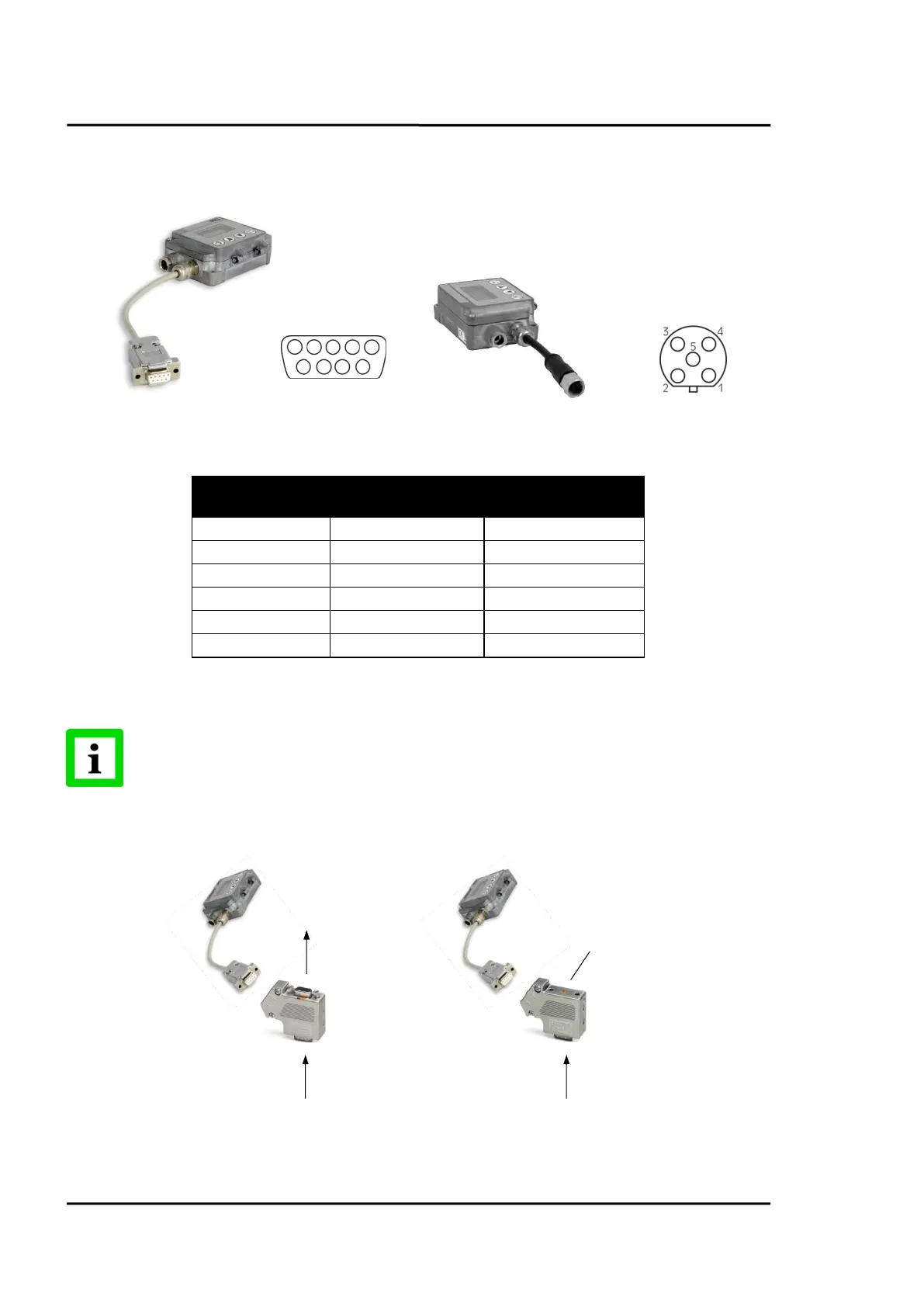
A Sub-D female connector or a M12 female connector can be ordered separately for Profibus. The M12
connector is B-coded. Please note the Sub-D connector is not IP rated!
Figure 77: Sub-D Connector (…P2) and M12 Connector (…P1)
Profibus
Sub-D Pin
(cable color)
M12 Pin
(cable color)
A (negative signal)
8 (green)
2 (white)
B (positive signal)
3 (yellow)
4 (black)
Shield
GND
5 (white)
3 (blue)
n.a.
+ 5 V
6 (brown)
1 (brown)
Figure 78: Profibus Pin Assignment for Sub-D / M12 Connector
The termination for Profibus networks must be realized externally by the user!
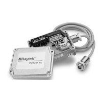
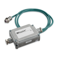
Figure 79: Exemplary Network with External Termination
1
5
4
3
2
6
9
7
8
Slave
n
Slave
n+1
Slave
n-1
Slave
n
Termination
Slave
n-1

Table of Contents

Questions and Answers:

Question and Answer IconNeed help?

Do you have a question about the RayTek MI3 and is the answer not in the manual?

RayTek MI3 Specifications

General IconGeneral
Spectral Response8 to 14 µm
Response Time500 ms
Display Resolution0.1 °C
Accuracy±1% or 1°C (2°F), whichever is greater
EmissivityAdjustable 0.10 to 1.00