31
ENGLISH
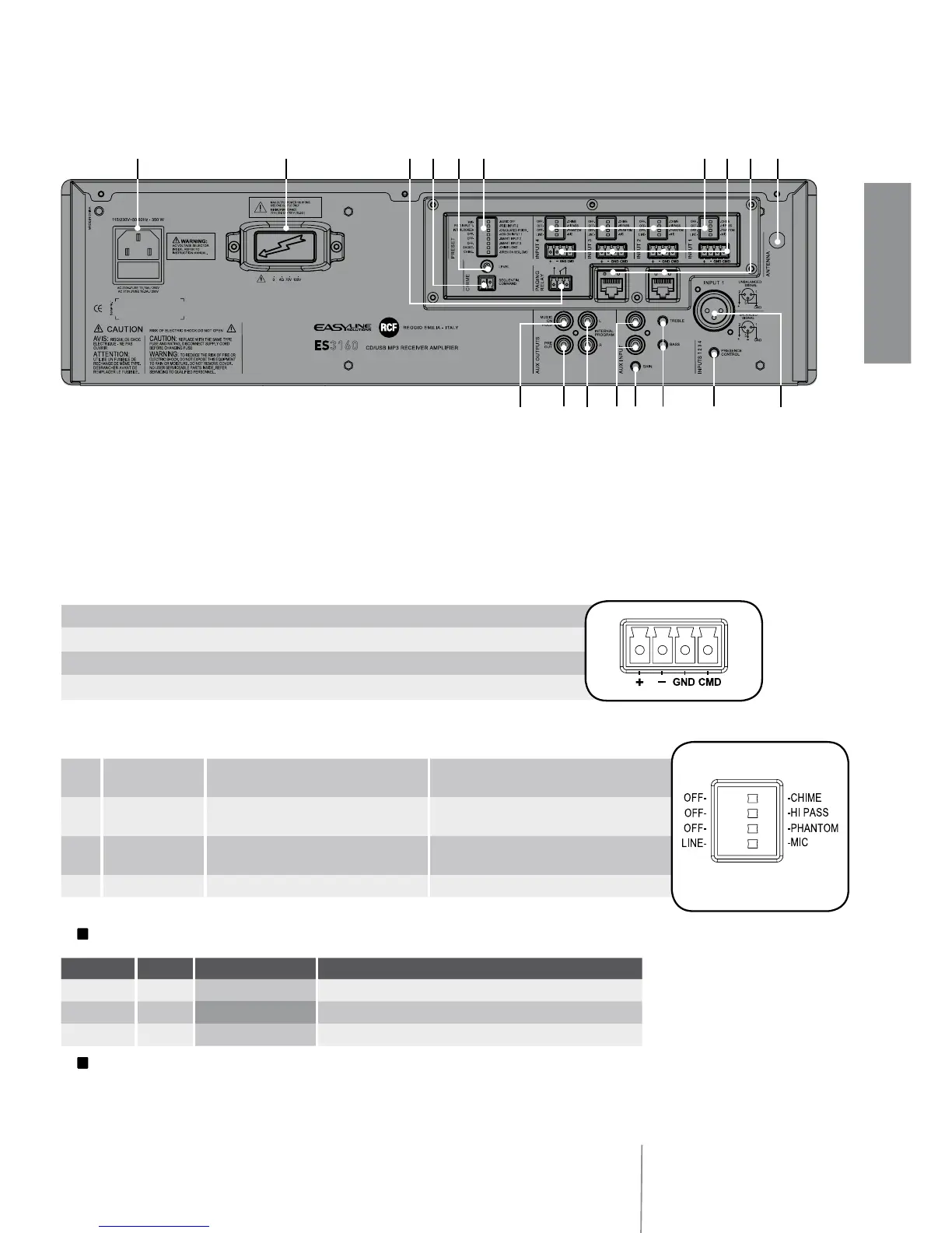
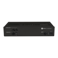
REAR PANEL
9 2 RJ 45 sockets (channels 2 and 3) to connect 1 RCF BM 3001 paging microphone
per socket.
Note: when a BM 3001 paging microphone is connected, it is necessary to set the
dip-switches 3 and 4 to MIC. PHANTOM (see 12 below) of the relevant channel.
0 Antenna input (the antenna is necessary when using the tuner).
{ 4 balanced audio inputs (channels 1, 2, 3, 4) with sockets for removable connectors.
} Each channel has 4 dip-switches:
L
Examples of dip-switches 3 and 4 settings:
L
When a BM 3001 paging microphone is used, it is necessary to choose the ‘MIC with
PHANTOM’ mode in the relevant channel (dip-switch no.3 set to PHANTOM; dip-switch no.4
set to MIC).
+ Hot audio input
– Cold audio input
GND ground
CMD command – priority access when connected to ground
1
OFF – CHIME OFF: the chime is disabled.
CHIME: the chime will be played as soon as a
priority command is activated.
2
OFF – HI PASS
OFF: the audio hi-pass filter is not inserted
(flat frequency response).
HI PASS: the audio hi-pass filter is inserted.
3
OFF – PHANTOM
OFF: the PHANTOM power supply is not
available on the relevant audio input.
PHANTOM: the PHANTOM power supply is
available on the relevant audio input.
4
LINE – MIC LINE: line audio input. MIC: microphone audio input.
DIP 3 DIP 4 MODE USE (EXAMPLES)
OFF
LINE LINE CD/MP3 players, tuners, message players, phone systems
OFF
MIC MIC Dynamic microphones
PHANTOM
MIC MIC with PHANTOM BM 3001 paging microphones, electret microphones
q
u
et
r w
i
9 0} {o[] pAS
y