EasyManuals Logo

RCS TZ43 User Manual

RCS TZ43
37 pages
To Next Page IconTo Next Page
To Previous Page IconTo Previous Page
Page #32 background imageLoading...
Page #32 background image
DCN 141-01128-04 10/6/08
32
HVAC SYSTEM CONNECTION
Standard Gas/Electric HVAC System Wiring
RED
GREEN
WHITE
YELLOW
TZ43 Thermostat
W1 HEAT
Installation Notes
Standard HVAC System Setup Notes:
Single Stage Systems use W1 for heating stage 1 and Y1 for cooling stage 1.
Two Stage Heating systems use W1 for stage 1 and W2 for stage 2 heating.
Two Stage Cooling systems use Y1 for stage 1 and Y2 for stage 2 cooling.
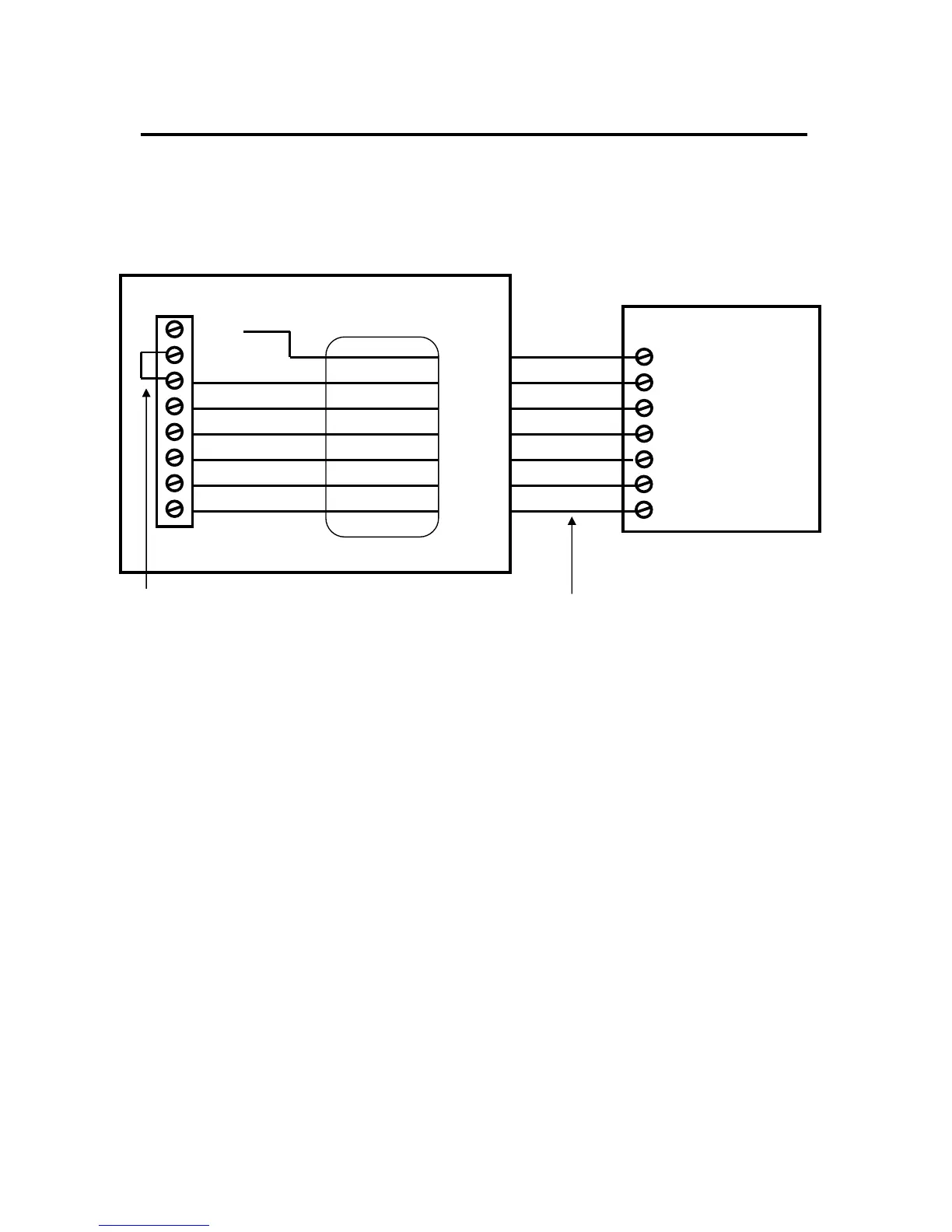
HVAC System 24VAC Transformer
If you have an integrated heating and cooling system with a single transformer, do NOT cut jumper
JP1. Wire the 24V Return (red) wire to either RH or RC. This is typical of most central systems.
If you have separate heating and cooling systems with separate transformers, cut jumper JP1.
Wire the heating 24V R (red) wire to the control unit’s RH terminal and run the cooling systems
24V R (red) wire to control unit’s RC terminal. Also wire the cooling systems 24VAC Com to
the control units 24VAC Com terminal.
IJP1: internal RC/RH
Jumper
See notes
24RC
ORANGE
BROWN
24RH
G FAN
W2/O
Y1 COMP
Typical HVAC system
thermostat wiring color codes.
Be sure to verify your systems
wiring color codes.
Y2 COMP
24COM
Standard HVAC System
G Fan
W 1 Heat Stage 1
Y1 Compressor Stage 1
R 24VAC RETURN
C 24VAC COMMON
THERMOSTAT CONNECTION
Y2 Compressor Stage 2
W2 Heat Stage 2
BLUE

Questions and Answers:

Question and Answer IconNeed help?

Do you have a question about the RCS TZ43 and is the answer not in the manual?

RCS TZ43 Specifications

General IconGeneral
BrandRCS
ModelTZ43
CategoryThermostat
LanguageEnglish

Related product manuals