DCN 141-01128-04 10/6/08
34
HVAC SYSTEM QUICK TEST
If you need to verify that the HVAC system is operational, you can perform the following test
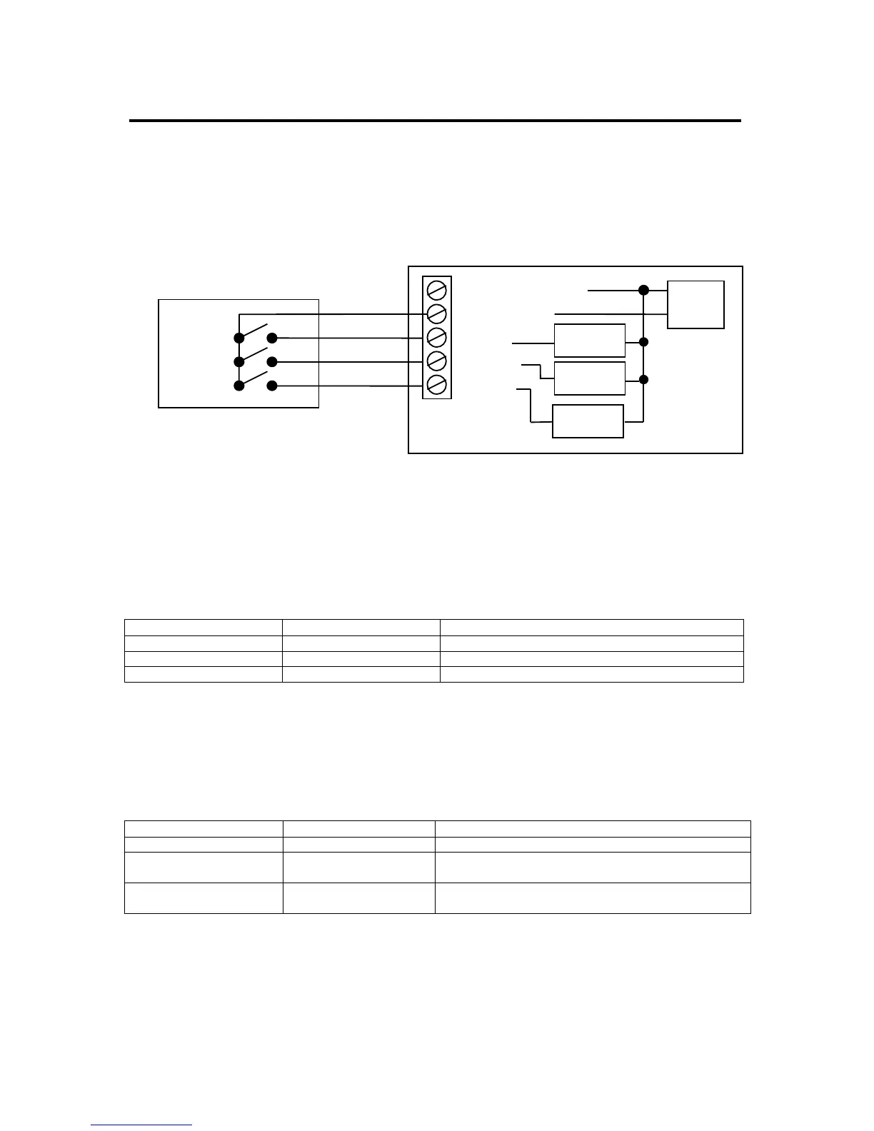
Thermostats, like the TZ43, are just switches to the HVAC system as shown in the diagram below.
This is a simplified example of a thermostat and a standard HVAC wiring diagram. The HVAC system
operation can be tested by duplicating the thermostat switch operation by shorting across the thermostat
terminals on the HVAC system.
Note: The HVAC system and thermostat connection voltage is 24VAC. This is a safe voltage to
work with but be careful to avoid shorting the 24VAC common (C) and 24VAC return (R) terminals.
This may blow a fuse in the HVAC system.
Standard HVAC System Quick Test
You can perform a quick test of the HVAC system by shorting across the appropriate thermostat terminals
on the HVAC thermostat connector. Use a short 6 inch wire to connect across the following terminals.
Function Test HVAC Terminals Result
Fan R to G Fan should come on
Heating R to W Heat cycle should start for heating
Cooling R to Y and G Compressor and Fan should start for cooling
Heat Pump System Quick Test
Similarly, you can test Heat Pump operation by shorting across the following terminals. Heat pump
operation is determined by compressor calls in conjunction with changeover (O) outputs. You must know
what your system CO type is (CO with Cool (typical) or CO with Heat). You should have configured the
TZ43 for correct CO type, refer to this setting. Heat Pump systems have an additional O terminal.
Function Test HVAC Terminals Result
Fan R to G Fan should come on
Heating R to Y and G Compressor and Fan should start and Heating
occurs.
Cooling R to Y and G and O Compressor and Fan should start.
CO valve operates and Cooling occurs.
HVAC SYSTEM
STANDARD GAS/AC
FAN
HEAT