EasyManuals Logo

RCS TZ43 User Manual

RCS TZ43
37 pages
To Next Page IconTo Next Page
To Previous Page IconTo Previous Page
Page #35 background imageLoading...
Page #35 background image
DCN 141-01128-04 10/6/08
35
Model TZ43
PN: 001-01652
Thermostat Wiring Diagram
HVAC System
Standard or
Heat Pump
Caution!
Set Installer Settings to
Correct System Type
24COM
24V RC
24V RH
Heat 1
*Heat 2
Fan
Y1
Y2
Optional
Remote
Temperature
Sensors
RC/RH Jumper JP1
Cut for separate
Heating and Cooling
Transformers
Typical Thermostat
Wiring Color Codes
RCS
HVAC SYSTEM
C - 24VAC Common
R - 24VAC Return
W1 – Heat Stage 1
W2/O* –
Heat Stage2
G – Fan
Y1 – Comp Stage 1
Y2 – Comp Stage 2
THERMOSTAT CONNECTOR
* for HP HVAC Systems
O=Changeover Valve
Green
Yellow
Blue
Red
White
Orange
Black
RS1
RS1
RS2
RS2
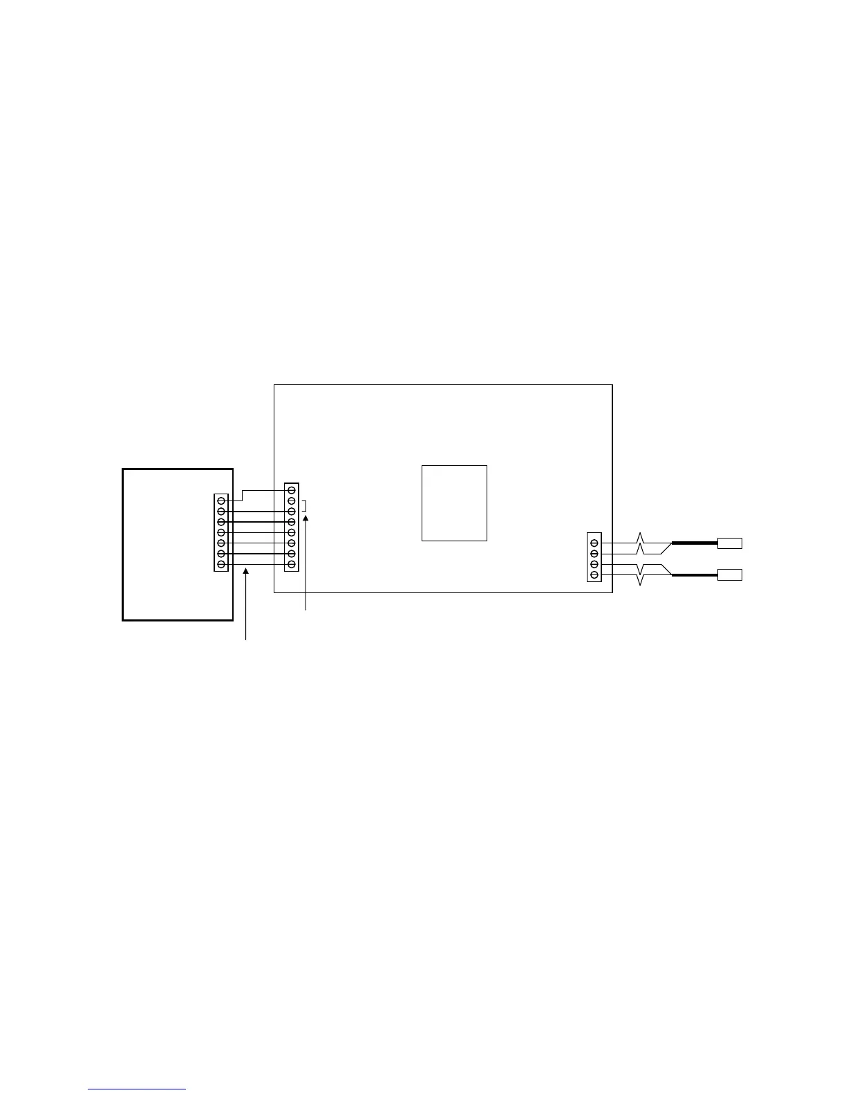
HVAC System Transformer
Most central HVAC systems have a common heating and cooling transformer. This is the factory default
setting for Jumper JP1. In some cases, you may have separate heating and cooling systems, each with their
own transformer. In that case, cut Jumper JP1 and wire the heating transformer red wire to the RH terminal
and the cooling system transformer red wire to the RC terminal. Wire the cooling system’s 24VAC Com to the
TZ43’s 24VAC Com terminal.

Questions and Answers:

Question and Answer IconNeed help?

Do you have a question about the RCS TZ43 and is the answer not in the manual?

RCS TZ43 Specifications

General IconGeneral
BrandRCS
ModelTZ43
CategoryThermostat
LanguageEnglish

Related product manuals