EasyManuals Logo

RCS TZ43 User Manual

RCS TZ43
37 pages
To Next Page IconTo Next Page
To Previous Page IconTo Previous Page
Page #33 background imageLoading...
Page #33 background image
DCN 141-01128-04 10/6/08
33
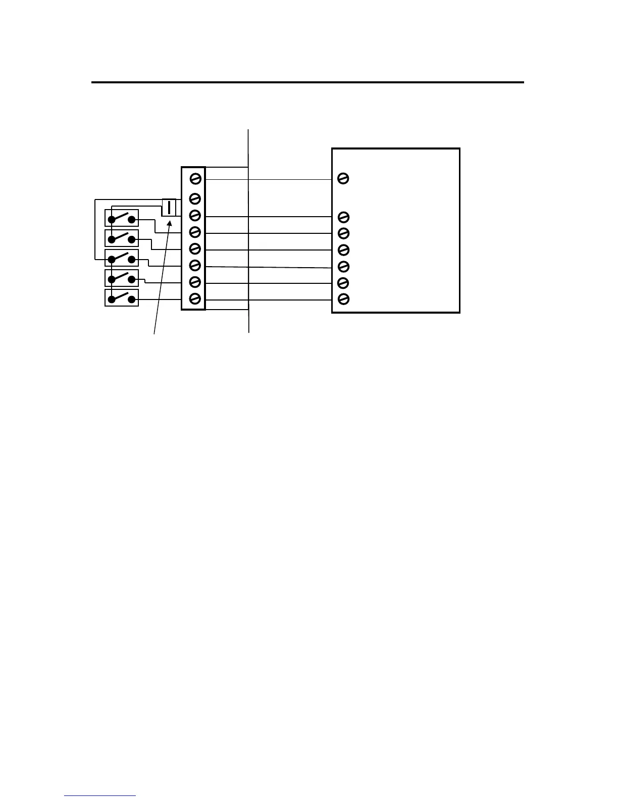
HVAC SYSTEM CONNECTION
Heat Pump HVAC System Wiring
Heat Pump HVAC System Setup Notes
Single Stage Compressor Systems use Y1 for stage 1 heating/cooling, and W1 for stage 2 heating (heat
strips).
Two Stage Compressor Systems use Y1 for stage 1, Y2 for stage 2 heating/cooling, and W1 for stage 3
heating (heat strips).
NOTE: You must configure the Changeover valve setting to work correctly with your HVAC
system. Changeover settings are made in the Installer Settings – System Settings - Mechanical
Settings menu. Changeover with cool is typical for most systems. Check your system
information to be sure. If you get cooling when you expect heating, change the C/O type to the
opposite setting.
W1 Aux Heat Stage 1
Y1 Compressor Stage 1
R 24VAC RETURN
Heat Pump HVAC System
RED
GREEN
WHITE
YELLOW
THERMOSTAT CONNECTION
TZ43
ORANGE
O/B Changeover (CO) Valve
24RH
Y2 Compressor Stage 2
G Fan
JP1
JP1: RH and RC Jumper. Do not cut.
Leave RH and RC connected for Heat Pump Systems
BROWN
W1
Heat
G Fan
W2/CO
Y1 Comp
HVAC SYSTEM
Y2 Comp
24RC
NOTE: Set correct Changeover
value operation for O (CO w/Cool)
or B (CO w/Heat) mode
24COM
C 24VAC COMMON
BLUE

Questions and Answers:

Question and Answer IconNeed help?

Do you have a question about the RCS TZ43 and is the answer not in the manual?

RCS TZ43 Specifications

General IconGeneral
BrandRCS
ModelTZ43
CategoryThermostat
LanguageEnglish

Related product manuals