4
VERBINDUNG ZUR STEUERUNG
4
CONNECTION TO CONTROL UNIT
4
CONNEXION A L'UNITE DE COMMANDE
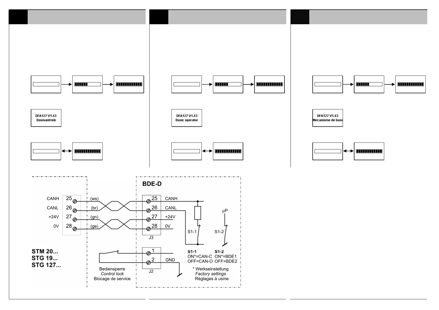
Anschluss an den CAN-Bus:
1)
Verbindungskabel am CAN-Anschluss (11) an-
schliessen und mit dem CAN-Anschluss der
Steuerung verbinden (Adern paarweise ver-
drillt).
Connection on CAN-bus:
1)
Plug in the connecting cable to the CAN-port
(11) and connect it to the CAN-port on the STG
(twisted-pair cable).
Connexion au bus CAN:
1)
Connecter le câble de raccordement au port
CAN (11) puis au port CAN de la STG
(conducteurs torsadés par paire).
Verbinden mit Steuerung…
Die Verbindung wurde hergestellt (Beispiel)
Keine Verbindung zur Steuerung
Connect to the control unit …
The control unit has been connected (example)
No connection to the control unit
Connecter avec unité de contrôle…
La connexion a été établie (exemple)
Aucune connexion établie avec la commande
S1-1
ON=CAN-C:
CAN-Abschluss
geschlossen
CAN termination
closed
Terminaison
Drahtfarben:
Wire colours:
Couleur des fils:
ws = weiss/white/blanc
br = braun/brown/brun
gn = grün/green/vert
ge = gelb/yellow/jaune
1)
DIP-Schalter (S1-1, S1-2) müssen vor dem
Anschliessen eingestellt werden!
Set the DIP-switches (S1-1, S1-2) before
connecting to the CAN-port!
Les commutateurs DIP (S1-1, S1-2) doivent
être réglés avant connexion avec le port
CAN!