8
2 INSTALLATION
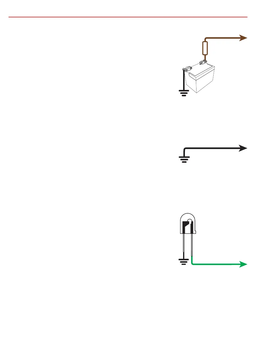
2.4 BROWN wire - Auxiliary Battery Positive
The BROWN wire should be connected to the auxiliary
battery’s positive terminal. This should be a maximum
of 1 metre in cable length from the battery. Appropriate
size fuses should be used as per the specifications
table on page 2.
2.5 BLACK wire - Common Ground
The BLACK wire should be connected to a ground
point that is common to both the Start battery (or the
Solar Input Ground wire) and the Auxiliary battery to
be charged. This point may be on the chassis of the
vehicle, on the chassis of the trailer/camper/caravan
or directly wired to both batteries, depending on your
installation requirements.
2.6 GREEN wire - Optional External LED Indication
The GREEN wire is provided to optionally connect an
external indicator LED which can be mounted away
from the unit (for example on the vehicle’s dashboard).
Connect the positive lead of the LED to the green wire,
and the negative lead to the common ground. No
external resistors are required.
The External LED will be ON when the unit is charging
and OFF when the unit is in standby mode or has no
power. Note: This output is not suitable for running a
globe.
Green Wire
Optional
LED
Brown Wire
Auxiliary
Battery
Midi
Fuse
Black Wire