9
2 INSTALLATION
2.7 Cable sizing
Below is a table outlining the required cable size for a given cable install length.
Always choose a wire diameter equal to or greater than what is specified below.
Part Number Cable Install Length
(m)
Recommended Wire
Size (mm²)
Closest (BAE, B&S,
AWG)
BCDC1225(-LV) 1 - 5 7.71 8
5 - 9 13.56 6
BCDC1240(-LV) 1 - 5 13.56 6
5 - 9 20.28 4
2.8 Wiring
The heavy gauge wires on the BCDC1225(-LV) and BCDC1240(-LV) unit carry
peak currents of up to 35 and 50 Amps respectively, and it is important to make a
good, low resistance, electrical connection that will not degrade over time. Failure
to make a good, reliable contact may result in breakdown of the wire insulation
and cause a short circuit, or worst case a fire. We recommend that this activity be
undertaken by an appropriately trained person.
REDARC recommends using a soldered butt splice crimp connection that is
covered with heatshrink. See Figure 2.8. REDARC does not recommend using
standard red/ blue/yellow blade connections as they are not rated for either the
current required or gauge of wire supplied on the unit.
Crimping provides good mechanical connection, soldering provides a long lasting
electrical connection and forming of the heatshrink will prevent any shorting/
contact with your vehicle chassis.
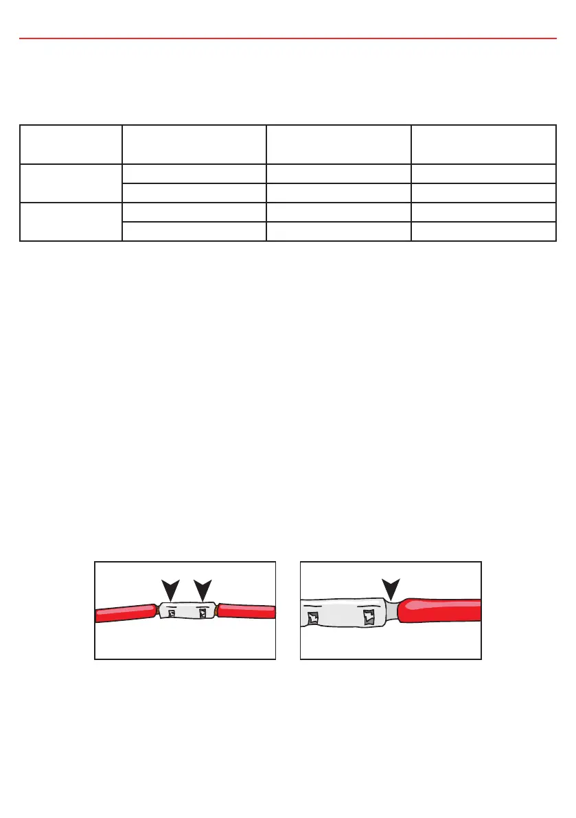
Figure 2.8 - Ensuring a good wiring connection
Crimp here.
Crimp both wires to the butt splice using
indent type crimpers.
Solder Both Ends Here.
Solder the wires to the butt splice.
Ensure that a good connection is
made. Keep heatshrink away until after
soldering is complete and has cooled.