EN English | 3
SPECIFICATIONS
Part Number SBI12 (*D) SBI24 (*D) SBI212 (*D) SBI224 (*D)
System Voltage 12 V 24 V 12 V 24 V
ON Volts 13.2 V 26.4 V 13.2 V 26.4 V
OFF Volts 12.6 V 25.4 V 12.6 V 25.4 V
Turn ON Delay 5 sec
Turn OFF Delay 10 sec
Max. Cont. Current 100 A 200 A
Max. Inrush Current 400 A 600 A
Standby Current <5 mA
Part Number SBI12 (*D) SBI24 (*D) SBI212 (*D) SBI224 (*D)
Dimensions
75×70×80 mm
(3"×2.8"×3.2")
90×95×100 mm
(3.5"×3.7"×3.9")
Weight 200 g (0.4 lbs) 600 g (1.3 lbs)
Warranty 2 years
Standards CE, C-Tick, AS/NZS CISPR11:2004, UKCA
*D indicates Dual Sensing Models.
Voltages Specied are ±0.1 V
PRIOR TO INSTALLATION
MOUNTING
Mount the Smart Start SBI securely in a convenient location near the start
battery bank.
Do not mount in direct engine heat.
RECOMMENDED FUSES
REDARC Fuse Kits are recommended as they contain high quality, reliable
fuses and fuse holders.
SBI12 / SBI24: FK60 MIDI 60 A Fuse Kit
SBI212 / SBI242: FK100 MEGA 100 A Fuse Kit
MIDI Fuse with Holder MEGA Fuse with Holder Fuse Assembly
CABLE SIZES
Model Wire Length Start Feature with Push button Override No Override Main Stud Torque
Circuit Breaker /Fuse Wire Circuit Breaker /Fuse Wire
SBI12/SBI24
Up to 3 m 100 A 19 mm² (4B&S) 60 A 8 mm² (8B&S) 5—6.2 Nm
3 m to 6 m 100 A 32 mm² (2B&S) 60 A 13 mm² (6B&S) 5—6.2 Nm
SBI212/SBI224
Up to 3 m 200 A 32 mm² (2B&S) 120 A 19 mm² (4B&S) 6.5 Nm max.
3 m to 6 m 200 A 40 mm² (1B&S) 120 A 25 mm² (3B&S) 6.5 Nm max.
INSTALLATION
Override
Wire
(BLUE)
Override
Wire
(BLUE)
Ground
Wire
(BLACK)
Mounting
Point
Mounting
Point
Ground
Wire
(BLACK)
Start
Terminal
Auxiliary
Terminal
Auxiliary
Terminal
Start
Terminal
STANDARD WIRING
Ensure adequately sized cable is used.
Ensure the auxiliary battery is properly grounded to a common chassis
earth point.
Ensure the SBI ground wire is making good contact with the chassis ground
point.
When using fuses make sure that the fuse makes a good low resistance
connection.
Fuse/Circuit Breaker ratings are dependent on the type of installation and
the size of the loads.
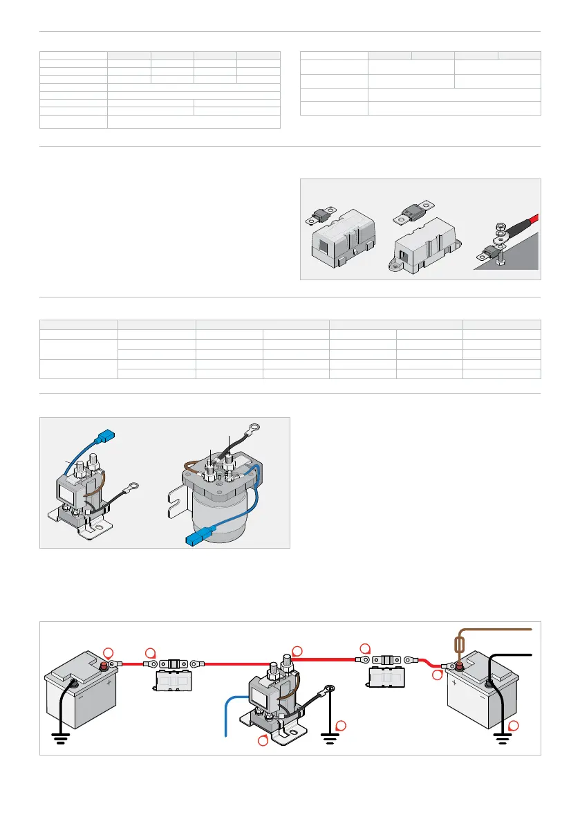
WIRING DIAGRAM
1. Make sure the auxiliary battery negative is properly grounded to the vehicle
chassis. (1)
2. Ground Connection. Connect the Smart Start SBI ground terminal to
chassis ground. Remove any paint to ensure a good ground connection.
NOTE: A good ground will ensure correct switching voltage. (2)
3. Select correct Circuit Breaker/Fuse sizes and install at battery end of both
positive cables. (3)
4. Connect the cables in the order shown below. (4, 5, 6, 7)
5
Fuse*
(with holder)
Start
Battery
Override
Wire
SBI
Circuit Breaker*
Loads
Auxiliary
Battery
Fuse*
(with holder)
2 1
3
3
6
4
7
 Loading...