Redback Technologies
Owner’s Guide – Redback Smart Inverter - v1.4 17
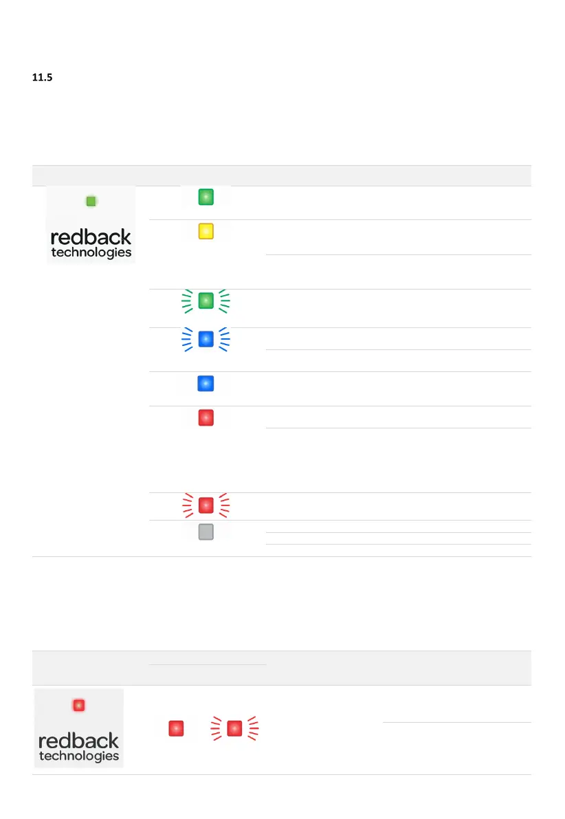
Inverter Status LEDs
The Inverter is equipped with a status LED on the front panel, and a Network status LED on the communications module. The
optional EMS Ethernet module also has an Ethernet status LED. The table below lists LED indications, probable cause, and
rectification steps.
11.5.1 INVERTER STATUS LED
Green ON
normally.
Yellow ON
OK. No action needed. Night mode is
de-activated automatically.
Preparing to connect to grid
OK. Self-testing in progress. No
action needed.
Green Flashing
Wait for start up to complete (about
one minute).
Blue Flashing
Inverter is advertising BLE
Use Redback Install app to connect
to the inverter.
Network communications
lost.
Use Redback Install app to
reconnect to the inverter.
Redback Install by BLE
Use Redback Install app to complete
setup
Red ON
Restart system. If fault persists,
contact Redback.
Emails sent to Redback customer
service team, the registered
installer, and the system owner.
Installer to investigate.
Email is also sent when the alarm is
Disconnected from grid due
to interlocked inverter fault.
Deal with faulted inverter. See
section 10.5.2 below.
OFF
Wait for power to be restored
Enable Grid Supply to Inverter
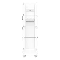
11.5.2 INVERTER STATUS LED (MULTIPLE-INVERTER INSTALLATIONS)
Your system may include multiple SI series inverters. The inverters are interlocked to ensure a fault on any inverter causes the
other inverters to shut down until the triggering fault is rectified, or the faulting inverter is completely powered off. Outside of
a fault event, each inverter will run independently.
inverter and grid-disconnect
on other inverters
Restart the faulting inverter. If it
restarts the other inverters will
automatically reconnect to the grid.
If the faulting inverter does not
restart, completely isolate the
inverter (PV ARRAY DC isolator OFF
and Grid AC isolator OFF). The other
inverters will reconnect to the grid.