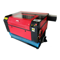
(Figure 5)
1: the main power switch: to control the total power supply off 2. Lamp switch: the lamp power
control equipment off 3: Laser switch: control equipment Laser-off 4: Power Supply Input 220V
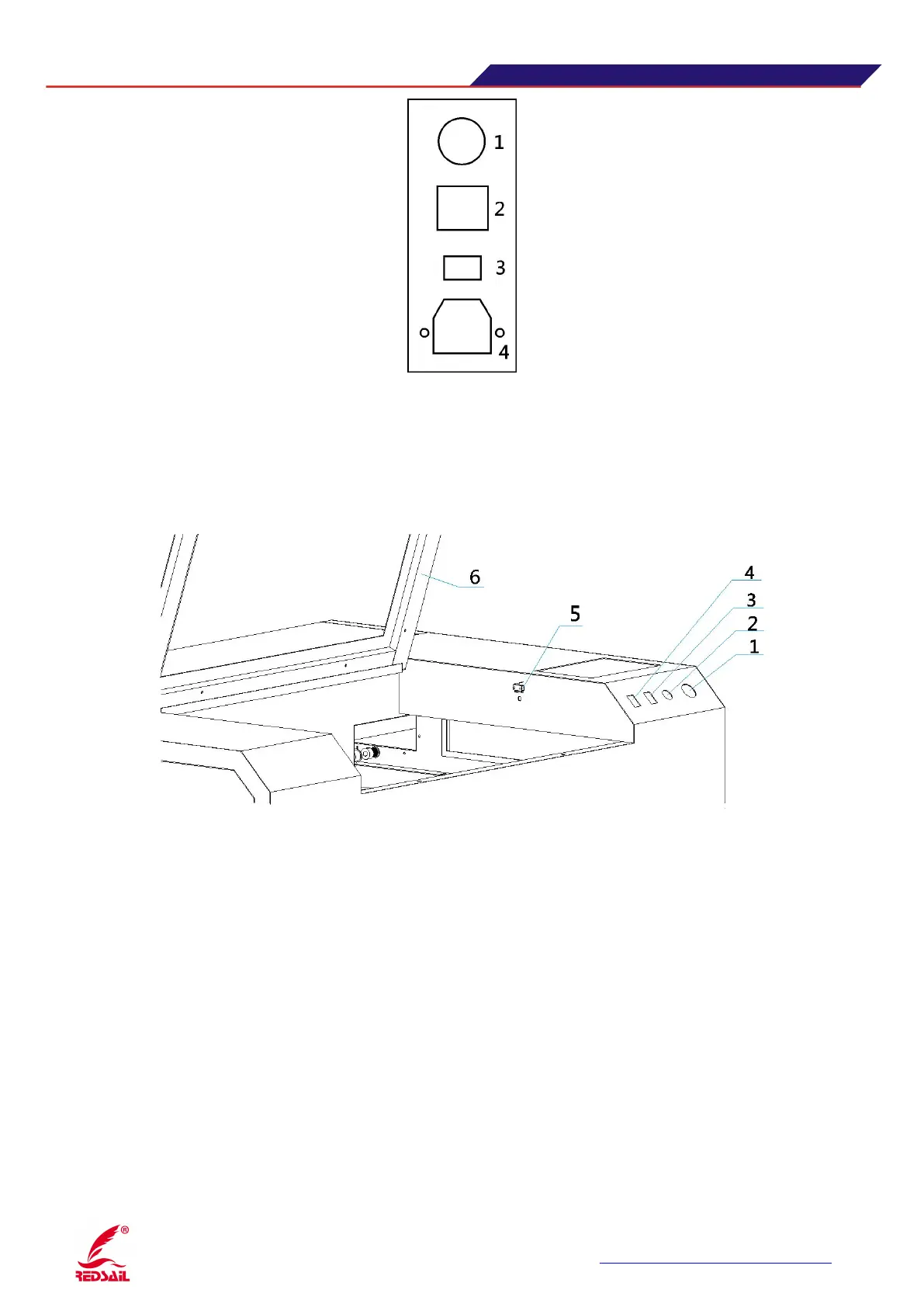
3.6 Sub-control switch zone description of the device
(
Figure 6
)
1.The total power control emergency stop switch, responsible for equipment (except lamp outside),
when the device abnormal situation, can quickly press the button, quickly cut off the power to the load
2. Cap protection knob, with shrapnel switch (5) and the cover door (6) work, when the key turn to the
right, the cover door off (contact dome switches) or turn on ,the machine will always on work. When
the key switch is turned on, when the lid closes, click on the panel "Continue" button, the machine
starts to work, when you open the lid, the device is paused.
3. The red indicator (optional), when the switch is turned on the red indicator light (mounted on the
laser head), play a fixed origin, indicating the position of the light effect.
4. temporarily empty
5. shrapnel switch
6. Cover the door
 Loading...