济南红帆科技有限公司
Redsail Tech Co., Ltd
h t t p : / / w w w . e a s y c u t . c n
Chapter Three Equipment Accessories Installations and
Instructions
3.1 Laser Tube installation
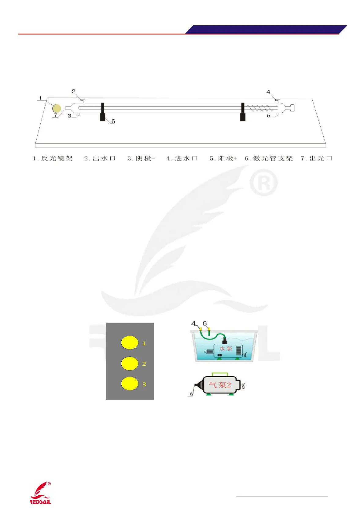
1.Reflective Mirror Stand 2.Water Outlet 3.Cathode- 4.Water Inlet 5. Anode+ 6.Laser Tube Stand 7.Laser Outlet
While installing laser tube , please refer to picture 1.According to picture 1 illustration, use electric
soldering iron to weld anode line(pink cord) and cathode rays(black/blue cord) in the Specified location(note:
Pay attention to not use electric iron welding on spot of the laser tube too long, in case the excess temperature
burnt laser tube),shall not be virtual welding. After completion of welding, operators should wrap it with high
After completion of welding, insert in/out tube respectively to the provisions of the laser tube outlet and
inlet position(While linking water tube,operators should follow principle that water inflow from the anode
and outflow from the cathode).
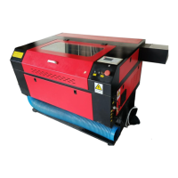
3.2 Water tube, air tube and air pump connections
1.Water Inlet 2.Water Outlet 3.Air Inlet 4.Water Outlet 5.Water Inlet 6.Air Outlet(Picture 2)
3.2.1 Water tube and water pump, air tube and air pump connections:
(1) Please full the tank with water before connecting(water level should be more than three-quarters
of the water tank, submerged pump).