NEEDLE
BAR
TIMING
GEAR
ASSEMBLY
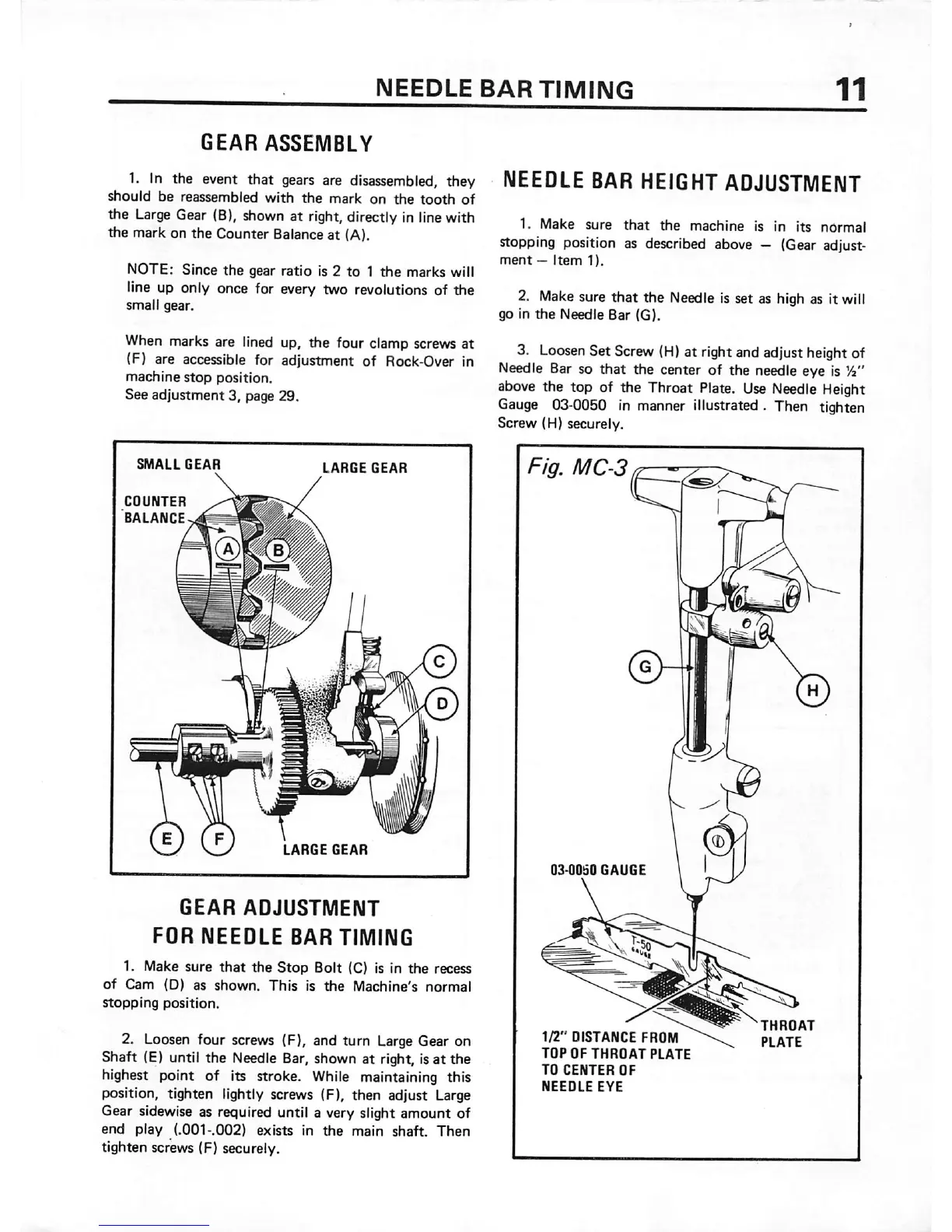
1. In the event that
gears
are
disassembled,
they
should be reassembled
with
the
mark on
the
tooth
of
the
Large
Gear
(B),
shown
at right,directly Inlinewith
the mark on the Counter Balance at (A).
NOTE: Since
the
gear ratio is 2
to
1
the
marks will
line up only once for every two revolutions of
the
small gear.
When
marks are
lined
up, the four clamp
screws
at
(F) are accessible for adjustment of Rock-Over In
machine
stop
position.
See adjustment 3, page 29.
m
I
i
GEAR
ADJUSTMENT
FOR
NEEDLE
BAR TIMING
1. Make sure
that
the
Stop
Bolt (C) is In
the
recess
of
Cam (D) as shown.
This
Is
the
Machine's
normal
stopping
position.
2. Loosen four screws (F), and turn
Large
Gear on
Shaft (E) until the Needle Bar, shown at right, isat the
highest point of its stroke.
While
maintaining this
position, tighten lightly screws (F), then adjust Large
Gear sidewise as required until a very slight amount of
end
play
(.001-.002)
exists
in
the
main
shaft.
Then
tighten screws (F) securely.
NEEDLE
BAR
HEIGHT
ADJUSTMENT
1. Make sure
that
the
machine is in its normal
stopping position as described above —
(Gear
adjust
ment
—
Item
1).
2.
Make
sure that the
Needle
is set as high as it will
go in
the
Needle Bar (G).
3.
Loosen
Set
Screw
(H)
at rightand adjust
height
of
Needle Bar so that the center of the needle eye is
Vi"
above
the top of the Throat
Plate.
Use
Needle
Height
Gauge
03-0050 in manner illustrated . Then tighten
Screw (H) securely.
Fig.
MC-3
RNTc , e
03-0060
GAUGE
1/2"
DISTANCE FROM
TOP
OF
THROAT
PLATE
TO
CENTER
OF
NEEDLE
EYE
THROAT
PLATE
 Loading...