BELT
SHIFTING
IMPORTANT: When making
the
adjustments on this
sheet be sure tfiat Plunger (A) Is engaged In
Hole.
(B)of
Shifter
Lever (C) as shovi/n. If
not,
press Push
Button
Inward
to
make
the
engagement
PUSH BUTTON ADJUSTMENT
With machine In normal
stopping
position, loosen
two
Nuts (E) and screw them inward or outward as required
on Push ButttMi
Stem
(F) until a clearance
of
1/32"
to
1/16"
exists
at
(D).
Then
tighten
Nuts (E) securely.
DRIVE
PULLEY
ADJUSTMENT
When
machine
Is in
normal
stopping
position
a
clearance
of
1/64"
should
exist
between
Leather
Brake
Shoe
(H)
and
side
of
Pulley
(G) as
shown.
To
adjust,
tip
machine
back
on
Its hinges, loosen
Screw
(J)
and
position
Brake
(K) in or
out
as required.
Then
tighten Screw (J)
securely.
BELT
SHIFTING
ADJUSTMENT
1. Use
5/16"
heavy type, round Leather Belting or
Round
Endless
Belting.
The Belt Shifter is designed for
these belts and other sizes will
not
operate efficiently.
See
page
22 for belt
specification.
Also
see
No.
9 on
page
27.
2. Line up Motor Pulley centrally with respect
to
a
plumb line dropped
between
the Idlerand
Drive
Pulley.
3. Make sure
that
the
clearance between
stop
bolt
and Cutting Cam on Drive Pulley is adjusted as
described on page
24,
paragraph 1.
4. Make
sure
that
the
Idler
and
Drive
Pulleys
are
accurately
aligned
as shown so that the rim of neither
pulley will extend beyond the other to retard the belt
shifting action.
Use
a straight edge as shown to check
this alignment If adjustment is necessary, shift position
of
Belt Guard as required within
the
limits
of
the
bolt
holes
In
the
machine
base.
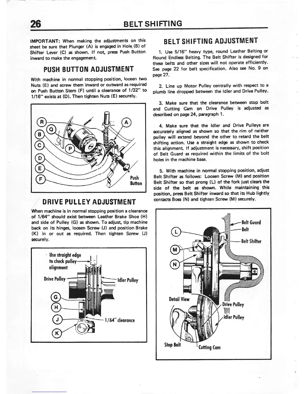
5. With
machine
in
normal
stopping
position,
adjust
Belt
Shifter
as
follows:
Loosen
Screw
(M)
and
position
Belt Shifter so
that
prong (L) of
the
fork just clears
the
side
of
the
belt
as shown. While maintaining this
position, pressBeitShifter inwardso that its Hub lightly
contacts
Boss (N)
and
tighten
Screw (M) securely.
Belt
Guard
Belt
BeltShifter
 Loading...