PARALLEL
INSTALLATION
Wood Screw
Washer
Rubber
Washer
Rubber
Bushing
Felt Pad
Knee Lever
Cham
Hook
may
be
attochedatfrontor
backscrewholes
to obtain more or
less
pedol
acKon
Length
of
Pedal
may
be adjustedto suit-;
operator's
foot
^ / L
END
OF
MACHINE
BASE
FLUSH
/ ®
WITH
EDGE
OF
BASE
SLOT.
APPROXIMATEY
2"-2y4"
1
FRONT
EDGE
OF
TABLE
Refer
to
page22
for
correct
belt
FootRail
1.
Accessory
box,
supplied
with
machine,
contains
all
necessary
items
for
installation^
2. Make sure
that
motor
specifications are
correct
for electrical
supply
and
that
the
Motor Pulley rotates
in
direction
of
arrow.
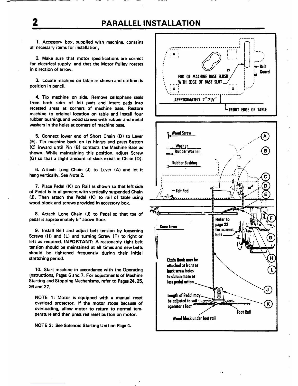
3.
Locate
machine
on
table
as
shown
and
outline
its
position
in pencil.
4.
Tip
machine
on side.
Remove
cellophane
seals
from
both
sides of felt
pads
and
insert
pads
into
recessed
areas
at
corners
of
machine
base.
Restore
machine
to
original
location
on
table
and
install
four
rubber
bushings
and
wood
screws
with
rubber
and
metal
washers
in
the
holes
at
comers
of
machine
base.
5.
Connect
lower
end
of
Short
Chain
(D)
to
Lever
(E). Tip machine back on its hinges and press Button
(C)
inward
until
Pin (B)
contacts
the
Machine
Base as
shown.
While
maintaining
this
position,
adjust
Screw
(G) so
that
a slight
amount
of slack exists in Chain (D).
6.
Attach
Long Chain (J)
to
Lever (A)
and
let it
hang
vertically.
See
Note
2.
7.
Place
Pedal
(K)
on
Rail
as
shown
so
that
leftside
of Pedal is in
alignment
with
vertically
suspended
Chain
(J). Then attach
the
Pedal (K) to rail of table using
wood
block
and
screws
provided
in
accessory
box.
8.
Attach
Long Chain (J)
to
Pedal so
that
toe
of
pedal
is
approximately
5"
above
floor.
9. Install Belt
and
adjust
belt
tension by loosening
Screws (H) and (L) and turning Screw (F) to right or
left as required. IMPORTANT: A reasonably
tight
belt
tension
should
be
maintained
at
all
times
and
new
belts
should be tightened frequently during
their
initial
stretching
period.
10.
Start
machine in accordance
with
the
Operating
Instructions, Pages 6
and
7.
For
adjustments
of Machine
Starting and Stopping Mechanisms, refer to Pages24,.25,
26
and
27.
NOTE 1; Motor is equipped
with
a manual reset
overload
protector.
If
the
motor
stops
because
of
overloading,
allow
motor
to
return
to
normal
tem
perature
and
then
press
red
reset
button
on
motor.
NOTE 2: See Solenoid Starting Unit on Page 4.
Woodblockunderfoot rail