NEEDLE
BAR
TIMING
TO
SET
NEEDLE
BAR
VIBRATOR
CAM
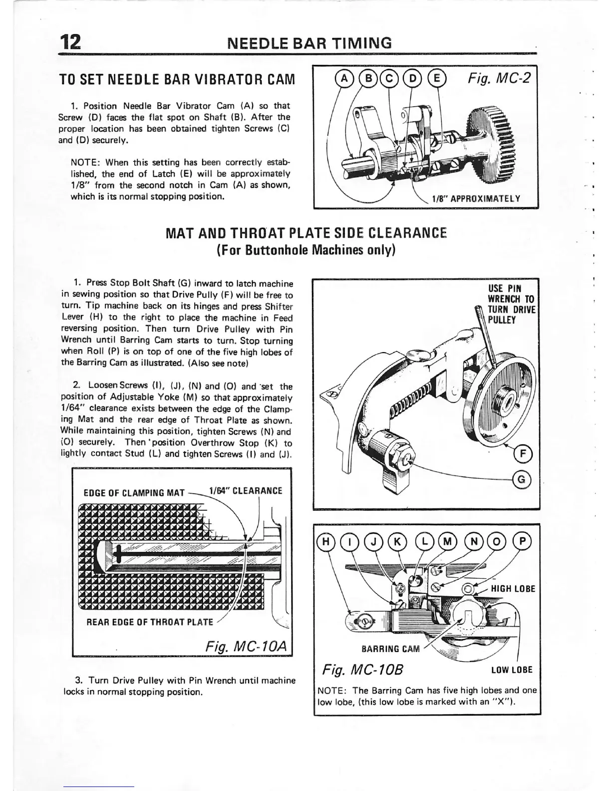
1.
Position
Needle
Bar
Vibrator
Cam
(A)
so
that
Screw
(D) faces
the
flat
spot
on
Shaft
(B).
After
the
proper location has been
obtained
tighten Screws (C)
and
(D)
securely.
NOTE:
When
this
setting
has
been
correctly
estab
lished,
the
end
of
Latch
(E) will be
approximately
1/8"
from
the
second
notch
in
Cam
(A) as
shown,
which
is its
normal
stopping
position.
a)
(i)©
(d) ®
Fig.
MC-2
l/B"
APPROXIMATELY
MAT
AND
THROAT
PLATE
SIDE
CLEARANCE
(For Buttonhole
Machines
only)
1. Press
Stop
Bolt
Shaft
(G)
inward
to
latch
machine
in sewing position so that DrivePully (F) will be free to
turn. Tip machine back on its hinges and press Shifter
Lever (H)
to
the
right
to
place
the
machine in Feed
reversing position. Then turn Drive Pulley with Pin
Wrench
until
Barring
Cam starts to turn. Stop turning
when Roll (P) is on
top
of one of the five high lobes of
the
Barring Cam as illustrated. (Also see note)
2. Loosen Screws (I), (J). (N)
and
(0)
and
set
the
position of Adjustable Yoke
(M)
so that approximately
1/64" clearance exists between the edge of the Clamp
ing Mat and the rear edge of
Throat
Plate as shown.
While maintaining this position, tighten Screv« (N) and
(O) securely. Then'position Overthrow Stop (K) to
lightly
contact
Stud
(L) and tighten Screws (I) and
|J).
•Trrrr
rrirrrrm.-
r r r r r
rrir
r ?
r r
rr
mr
rrrrrr
r r r r
ra
rrrrrrrrrrrrriTiJ'rrj'rr
pr
er
jprcw
«r
jr
^
KT^
rrrrrrrmrrrrrrrrrrrrrrr
REAR
EDGE
OF
THROAT
PLATE
Fig. MC-10A
3.
Turn
Drive Pulley
with
Pin Wrench
until
machine
locks In
normal
stopping
position.
BARRING
CAM
Fig.
MC-10B
LOW
LOBE
NOTE:
The
Barring Cam has five high lobes
and
one
low lobe, (this low
lobe
is
marked
with
an
"X").
 Loading...