42
10. Setting up the chassis
Beforethersttestdrive,thechassismustbecheckedand,ifnecessary,adjusted.
Therelationshipbetweenchassissetupanddrivingbehaviourisverycomplexandbeyondthescopeoftheseoperat-
ing instructions. For this reason, we can only show the setting options provided.
For further information, refer to relevant specialised magazines as well as comprehensive reference books on the
subject matter.
a) Conguring the camber
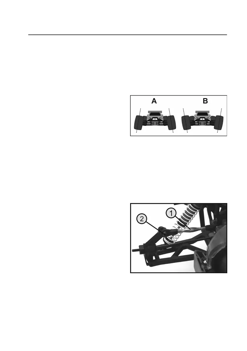
The camber is the inclination of the wheels as viewed from
the front (vertical).
A negative camber means that the wheels have their up-
per edges facing inwards (see Figure 2A).
A positive camber means that the wheels have their upper
edges facing outwards (see Figure 2B).
The conguration of the wheels in the two illustrations
showninFigure2isexaggeratedtoclearlyshowthedif-
ference between a negative and a positive camber.
Extremesettingsshouldbeavoidedwhenconguringthemodelvehicle.
A negative camber on the front wheels increases the cornering forces of the wheels when performing turning manoeu-
vres. The steering responds more directly and the steering forces are lower. At the same time, the wheel is pushed
ontotheaxleleginthedirectionoftheaxis.Thisreducesaxialbearingclearanceandmakesthedrivingbehaviour
smoother.
A negative camber on the rear wheels reduces the tendency of the rear of the vehicle to swing when turning corners.
However, a positive camber reduces the cornering forces of the tyres and should not be used.
Therearaxlecanbeconguredbyadjustingthelength
of the upper suspension arm (1). Because the adjusting
screws of the upper suspension arms have left and right-
hand threads, there is no need to remove the suspension
arms for adjustment. Just turn the screw either to the left
or right to adjust the length of the suspension arms.
If necessary, remove the screw on the steering knuckle
(2) and screw it into another hole. The adjusting screw of
thesuspensionarmcanthenbeusedforneadjustment.
Ifyouplacethemodelvehicleonaatsurface,youcan
easily check whether a wheel has a positive or negative
camber by using a large triangle ruler or an angle.
Figure 2
Figure 3