EasyManuals Logo

Reer EOS4 Installation, Use And Maintenance

Reer EOS4
40 pages
To Next Page IconTo Next Page
To Previous Page IconTo Previous Page
Page #16 background imageLoading...
Page #16 background image
EOS4 SAFETY LIGHT CURTAIN
8540733 • 23/03/2016 • Rev.17 15
English
Electrical connections
Before making electrical connections, make sure that the mains voltage matches the one
indicated in the technical data.
The Emitter and Receiver must be powered at a 24Vdc±20% (PELV, in compliance with
the standard EN 60204-1 (Chapter 6.4)).
The electrical connections must be made according to the wiring diagrams provided in
this manual.
In particular, do not connect other devices to the connectors of the Emitter and Receiver.
To guarantee reliable operation using a diode bridge power supply unit, its output
capacity must be at least 2000F for each A absorbed.
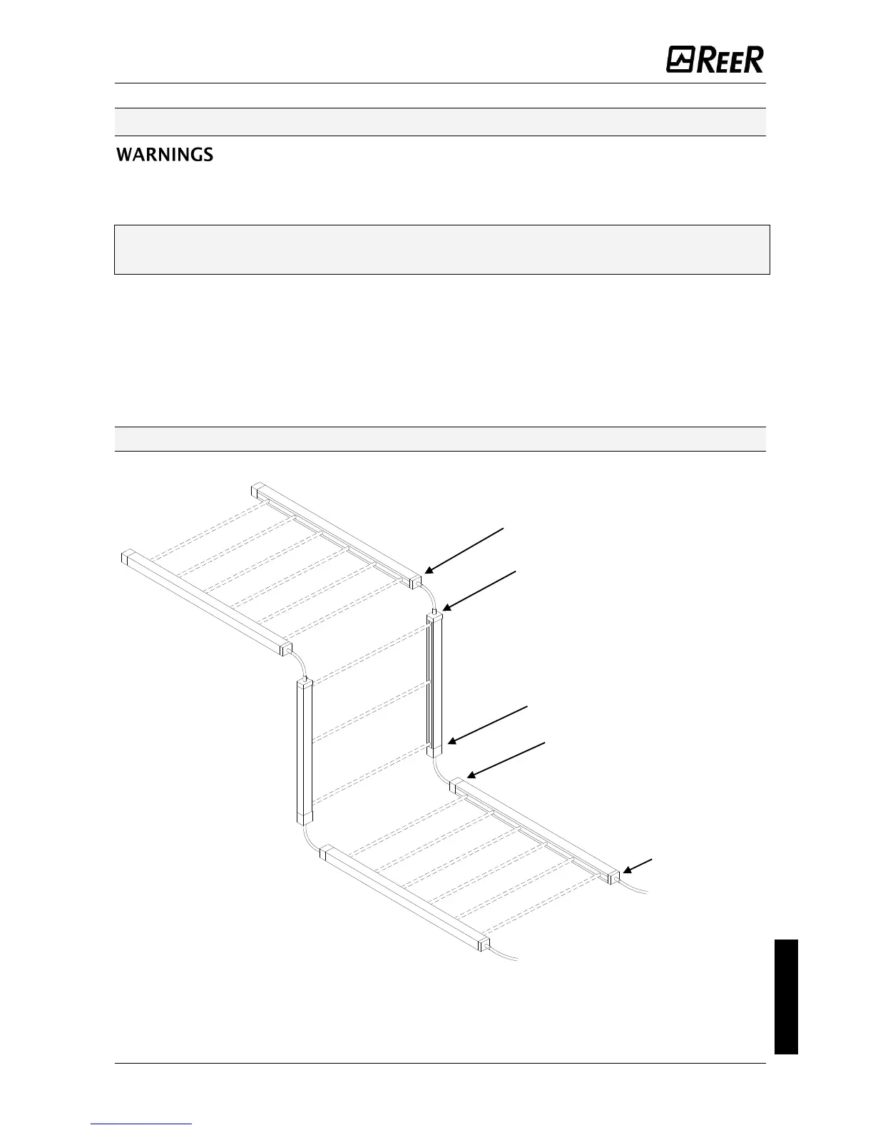
Layout of the connectors on MASTER/SLAVE light curtain
Figure 16 - Connector layout
SLAVE primary connector
SLAVE2 secondary connector
SLAVE
SLAVE 2
SLAVE2 primary connector
MASTER secondary connector
MASTER
MASTER primary
connector

Other manuals for Reer EOS4

Questions and Answers:

Question and Answer IconNeed help?

Do you have a question about the Reer EOS4 and is the answer not in the manual?

Reer EOS4 Specifications

General IconGeneral
Power Supply24 VDC ±20%
Resolution14 mm
Safety CategoryType 4
Operating Temperature+55 °C
Protection RatingIP65
Detection CapabilityOpaque objects
ConnectionM12 connector
Response Time≤ 20 ms
Outputs2 x safety outputs (OSSDs)

Related product manuals