6
reflex ’servitec’
Installation
Note:
Please check the delivery for completeness and damage immediately after goods receiving! Transport damage must be
notified immediately!
The scope of delivery is described on the delivery note and the content indicated on the cardboard box.
(→ p. 3)
1 Pallet with outer cardboard box with - ’servitec’ (pre-assembled)
(content indicated on the outer - vacuum spray-tube (added in cardboard box)
cardboard box) - dipstick tube-deaeration unit (added in cardboard box)
with - foil pocket (attached to the ’servitec’) with
- installation, operating and maintenance instructions
- electric wiring diagram
Possible accessories:
1 cardboard box
- 'fillset' with water meter (added in cardboard box)
1 cardboard box
- 'fillset' with contact water meter (added in cardboard box)
Installation room requirements:
− Frost-free well-ventilated room, room temperature > 0 to max. 45 °C
− No unauthorized access
− Level floor with adequate load capacity with drainage facility
− Filling connection ND 15, according to DIN 1988 T 4
− Electrical connection to 230 V~, 50 Hz, 16 A with upstream fault
current protection switch: triggering current 0.03 A
− Remove ’servitec’ from the pallet and transport to the place of installation,
ensuring that the ’servitec’ is carried by the frame.
− When aligning the control unit ensure that the valves and feed facilities of
the connection lines can be operated.
− Install vacuum spray-tube (20) (nut M12).
− Connect the union nut of the suction connection (17) with the pump (10)
without any stress; insert the enclosed plastic washers if required.
− Connect connection hose (15) to manifold (9).
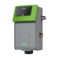
− Remove transport lock of the dipstick tube-deaeration unit (18) (see figure)
and manually screw in dipstick tube-deaeration unit (18).
− Retighten all screw connections.
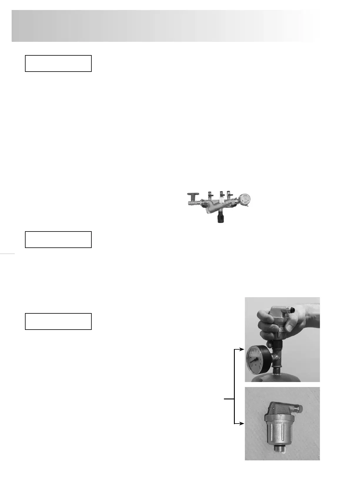
− When replenishing from the potable water system the 'fillset' (→ p. 3)
or a system separator must be installed upstream.
− If no ’fillset’ is intended for connection to the potable water system, a dirt
trap (mesh size < 0.25 mm) must be installed upstream by the customer.
− If automatic make-up is not connected, the connection (R) of the
make-up line must be blanked off with a plug G
1
/
2
".
Scope of delivery
Place of installation
Installation