≥ 500
Main flow V
circuit water
rich in gas
low in gas
7
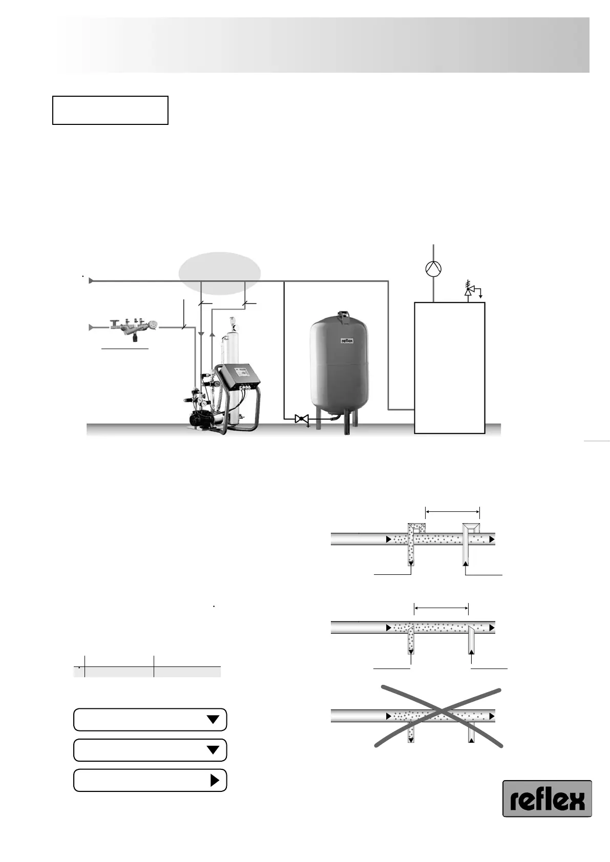
reflex ’servitec’
Installation
− connect ’servitec’ with the system piping. The maximum permissible media temperature at the connection
point is 70 °C (’servitec .../90 °C’ are applicable up to 90 °C), which is why it is installed in the system return
in the case of heating systems.
− connect in the immediate vicinity of the expansion line so that protection by way of the system safety valve
is provided. Otherwise, additional protection will be required.
− maintain a minimum distance between the connection points of 500 mm,
− note flow direction,
− rinse pipelines.
Installation diagrams
− Caution dirt! Connect connection lines from the top
or as immersion pipe as shown. Never integrate edgeless
from below (danger of contamination).
− With ’servitec .../gl’ a dirt trap (mesh size 0.25 mm) must
be provided in the overflow line O by the customer in
order to protect the additional solenoid valve (7) from
contamination.
− ’servitec’ deaeration operation is ensured only if ’servitec’
is connected to a representative main flow of the system.
The following minimum flow rates V must be maintained
during operation.
− Use the following pipe dimensions:
R
O P
reflex ’fillset’
with potable water
make-up
reflex ’servitec’ Expansion vessel/
pressure maintenance
Detail
connection
20 2520
V
pSV
Dewatering
by customer
max. 70 °C
Detail connection
R Make-up line
O Overflow line
P Pump line
V
servitec ... / 35
0.7 m³/h
servitec ... / 60
1.1 m³/h
≥ 500
Main flow V
circuit water
rich in gas low in gas
from above
from below as
immersion pipe
or laterally
welded edgeless
from below
not allowed
DN 25
DN 20
DN 20