8
reflex ’servitec’
Installation
Preferably install ’servitec’ on the
system side so that the temperature
exposure remains ≤ 70 °C.
When using softening systems, this
should be installed between ’fillset’
and ’servitec’.
If the shut-off at the connection point
of ’servitec’ is closed when shutting
down the circulating pumps, part flow
deaeration remains operational.
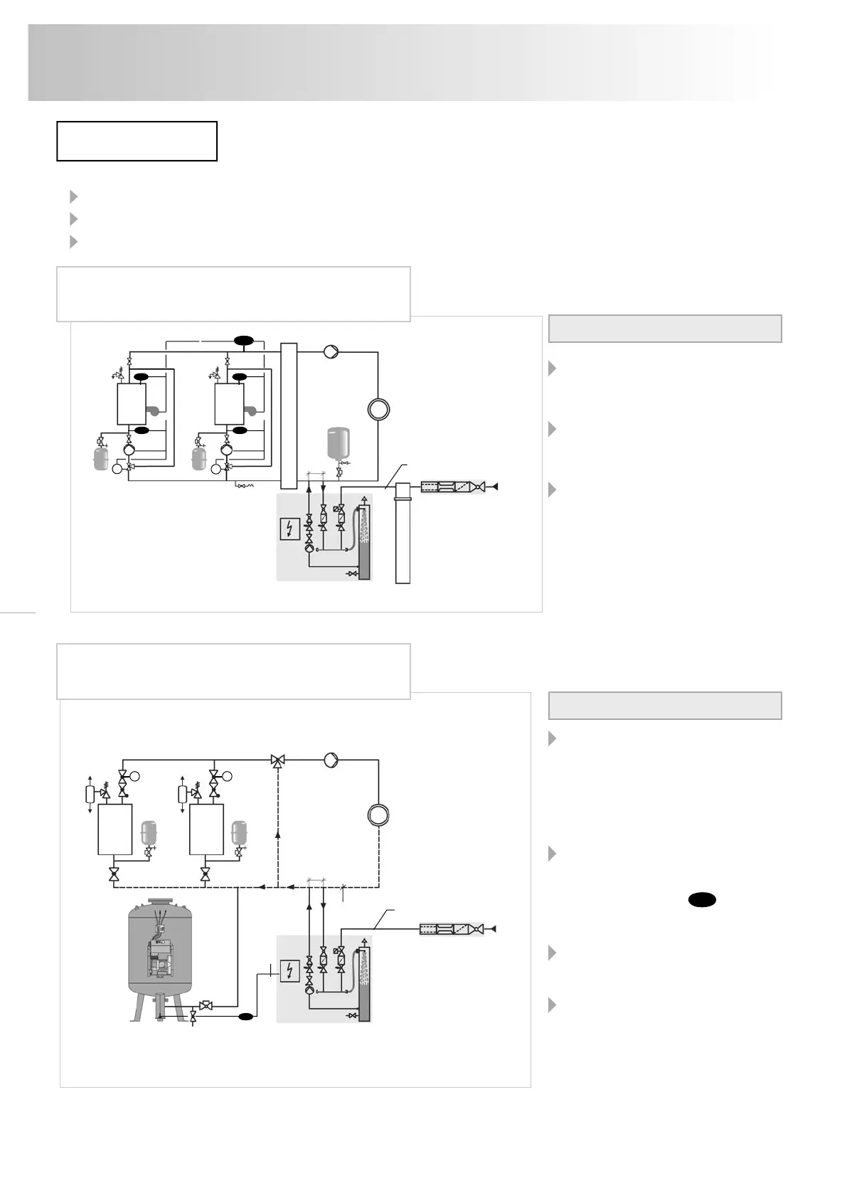
Notes to the installer:
reflex ’servitec magcontrol’ in a multiple boiler
system with hydraulic points and expansion vessel
The combination ’servitec’ with com-
pressor-controlled pressure-maintai-
ning stations (e.g. ’reflexomat’) is
especially recommended. The system,
which was highly degassed by the
’servitec’, is softly cushioned by the
’reflexomat’.
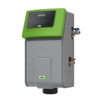
The water level in the expansion ves-
sel is monitored by the control unit of
the pressure maintaining station. The
230 V make-up signal LS of the
pressure maintaining station triggers
the make-up process with deaeration.
Optimum deaeration operation is en-
sured by connecting ’servitec’ in the
main circuit water flow.
On combining pump-controlled pre-
ssure maintaining stations with ’ser-
vitec’, we always recommend indivi-
dual boiler protection with a diaphragm
pressure expansion vessel
(e.g. ’reflex’).
Notes to the installer:
reflex ’servitec levelcontrol’ and compressor
pressure maintenance - an ideal combination
reflex ’servitec’ deaeration stations solve „gas problems“ in three ways:
no direct drawing in of air through controlled pressure maintenance
no circulation problems through free bubbles in the circuit water
reduction of corrosion risk through oxygen withdrawal from the filling and make-up water
* Detail connection → p. 7
The circuits must be adjusted to suit local conditions.
reflex ’fillset’
reflex ’servitec magcontrol’
Softening
Potable
water
M
M
TIC
TIC
TIC
TIC
TIC
M M
Hydraulic points
202025
≥ 500*
≥ 500*
reflex ’fillset’
reflex ’servitec levelcontrol’’reflexomat’
Potable
water
202025
230 V
Signal
Cable by
customer
Main volumetric flow
Required flow pressure ≥ 1.3 bar
Required flow pressure ≥ 1.3 bar
LS
Installation diagrams