Variomat Basic — 22.07.2020 - Rev.A
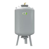
7.4.1.3 Use in a system with central return flow admixture
Degassing line
• For gas-rich water from the system.
• For degassed water into the system.
Make-up with water via a softening system.
• Always integrate the device in the "V" main volume flow to ensure
degassing the system water. It is the system side in systems with
central return flow admixture or hydraulic switching points. The
vessel of the heat generator must be fitted with an individual
protective device.
• When using Reflex Fillsoft softening systems, always install the
Fillset Impulse.
– The device controller evaluates the make-up quantities and
signals a required replacement of the softening cartridges.
Note!
The quality of the make-up water must comply with the
applicable standards such as VDI 2035.
7.5 Electrical connection
Risk of serious injury or death due to electric shock.
If live parts are touched, there is risk of life-threatening injuries.
• Ensure that the system is voltage-free before installing the
device.
• Ensure that the system is secured and cannot be reactivated by
other persons.
• Ensure that installation work for the electric connection of the
device is carried out by an electrician, and in compliance with
electrical engineering regulations.
The following descriptions apply to standard systems and are limited to
the necessary user-provided connections.
1. Disconnect the system from the power source and secure it
against unintentional reactivation.
2. Remove the cover.
DANGER Risk of serious injury or death due to electric shock.
Some parts of the device's circuit board may still be live with 230 V
even after the device has been physically isolated from the power
supply by pulling out of the mains plug. Before you remove the
covers, completely isolate the device controller from the power
supply. Verify that the main circuit board is voltage-free.
3. Install a screwed cable gland suitable for the respective cable. M16
or M20, for example.
4. Thread all cables to be connected through the cable gland.
5. Connect all cables as shown in the terminal diagram.
– For installer supplied fusing, comply with the connected loads
of the device , see chapter 6 "Technical data" on page 9 .
6. Install the cover.
7. Connect the mains plug to the 230 V power supply.
8. Activate the system.
The electrical connection is completed.
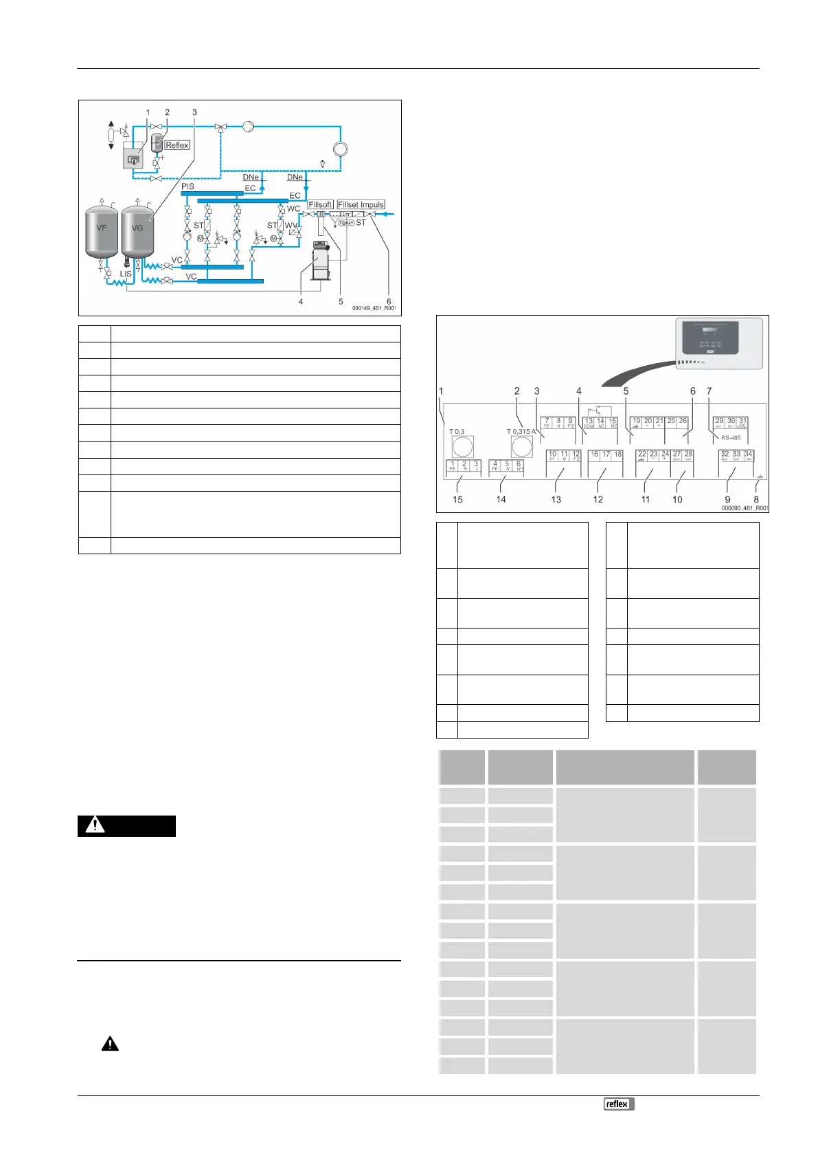
7.5.1 Terminal diagram
"L" fuse for electronics and
solenoid valves
Digital inputs
• Water meter
• Insufficient water
"N" fuse for solenoid
valves
Motor ball valve (energy
connection)
Overflow valve (not for
motor ball valve)
Optional for second
pressure value
Motor ball valve (control
connection)
230 V power supply via mains
cable and plug.
Pump for maintaining the
pressure.
Overflow solenoid valve
• Not used in a standard
device.
Valve for control of water
make-up.
Group message (floating).