Variomat Basic — 22.07.2020 - Rev.A
• Make-up setting values exceeded.
• Switches the following messages in the device controller:
• "ER 06", Make-up time
• "ER 07", Make-up cycles
• "ER 11", Make-up quantity
• "ER 15", Make-up valve
• "ER 20", Maximum make-up quantity
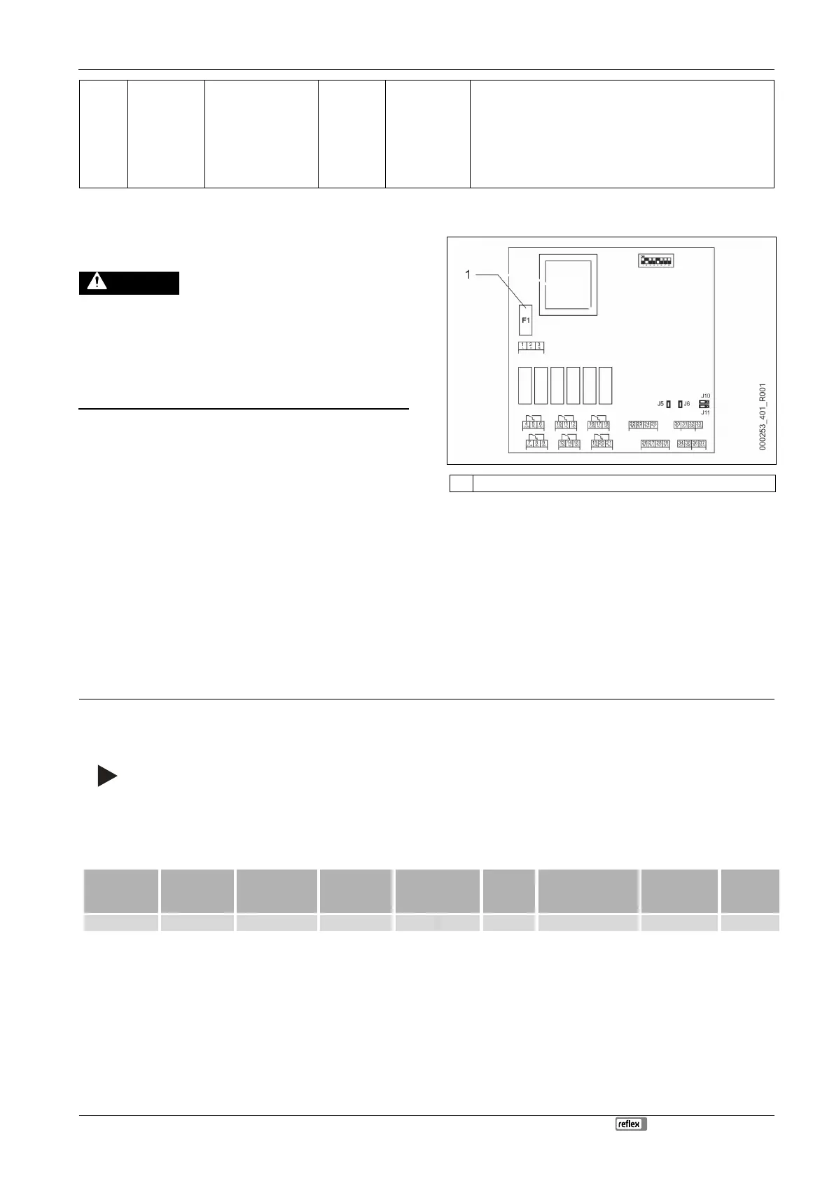
5.3 Replacing the fuses
Risk of electric shock!
Risk of serious injury or death due to electric shock. Some parts of
the main board may still carry 230 V voltage even with the device
physically isolated from the 230 V power supply.
• Before you remove the covers, completely isolate the device
controller from the power supply.
• Verify that the main circuit board is voltage-free.
Fusing is provided on the I/O module's main circuit board.
Microfuse F1 (250 V, 0, 16 A slow)
Proceed as follows:
1. Disconnect the I/O module from the power supply.
• Pull the power plug from the bus module.
2. Open the terminal space cover.
3. Remove the housing cover.
4. Replace the defective fuse.
5. Re-attach the housing cover.
6. Close the terminal space cover.
7. Reconnect the power supply for the module.
The fuse replacement is completed.
6 Technical data
6.1 Control unit
Note!
The following values apply for all control units:
– Permissible flow temperature:
– Permissible operating temperature:
– Permissible ambient temperature:
120 °C
70 °C
0 °C – 45 °C
Power supply
(V / Hz , A)
Number of RS-
485 interfaces
Electrical voltage
control unit
(V, A)