EasyManuals Logo

Reflex Variomat Basic User Manual

Reflex Variomat Basic
30 pages
To Next Page IconTo Next Page
To Previous Page IconTo Previous Page
Page #7 background imageLoading...
Page #7 background image
I/O module (optional expansion module)
Variomat Basic 22.07.2020 - Rev.A
English 7
Terminator settings
Jumper / Switch
Settings
I/O module
Control Basic
Jumper J10
Activated
X
---
and J11
Deactivated
---
---
DIP switch 1
Activated
---
X
and 2
Deactivated
---
---
Jumper J3
1 and 2 as well
as
Activated
---
X
3 and 4
Deactivated
---
---
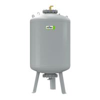
Device controller with I/O module and bus module
1
I/O module
3
"Control Basic" controller
2
Bus module
Terminator settings
Jumper /
Switch
Settings
I/O module
Control
Basic
Bus module
Lon Works
Profibus DP
Ethernet
Jumper
J10
Activated
---
---
---
and J11
Deactivated
X
---
---
DIP
switch 1
Activated
---
X
---
and 2
Deactivated
---
---
---
Jumper J3
1 and 2 as
well as
Activated
---
X
X
3 and 4
Deactivated
---
---
---
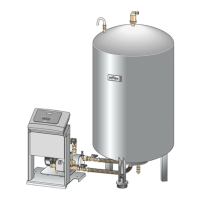
Device controllers and I/O module in Master-Slave function
1
Control Basic controller in
Master function
3
Control Basic controller in
Slave function
2
I/O module for the Master
function
4
I/O module for the Slave
function
Master function
Terminator settings
Jumper /
Switch
Settings
I/O module
Control Basic
Jumper J10
Activated
X
---
and J11
Deactivated
---
---
DIP switch 1
Activated
---
X
and 2
Deactivated
---
---
Jumper J3
1 and 2 as
well as
Activated
---
X
3 and 4
Deactivated
---
---
Slave function
Terminator settings
Jumper /
Switch
Settings
I/O
module
I/O module
for
expansion
Control
Basic
Jumper J10
Activated
---
X
---
and J11
Deactivated
X
---
---
DIP switch 1
Activated
---
---
X
and 2
Deactivated
---
---
---
Jumper J3
1 and 2 as
well as
Activated
---
---
X
3 and 4
Deactivated
---
---
---
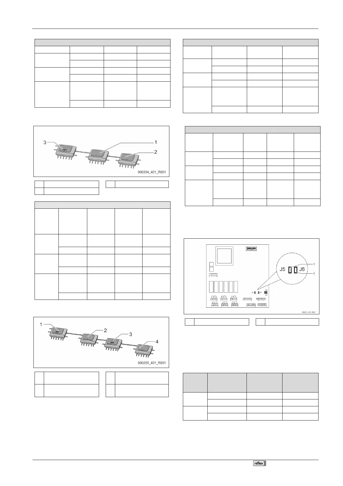
5.2.2 Setting the analogue outputs
Setting of the analogue outputs on the I/O module's main circuit board
1
Jumper J5
2
Jumper J6
Use the jumpers J5 and J6 to set both analogue outputs as current
outputs.
Proceed as follows:
1. Pull out the mains plug of the I/O module.
2. Open the housing cover.
3. Plug the jumpers in the required position.
Analogue
outputs
Jumper settings
Current output*
0 20 mA or
4 20 mA
Voltage output
0 - 10 V or
2 - 10 V
Analogue
output 1
J5 is plugged
---
X
J5 is not plugged
X
---
Analogue
output 2
J6 is plugged
---
X
J6 is not plugged
X
---
* Depending on the relevant setting in the device controllers

Table of Contents

Questions and Answers:

Question and Answer IconNeed help?

Do you have a question about the Reflex Variomat Basic and is the answer not in the manual?

Reflex Variomat Basic Specifications

General IconGeneral
BrandReflex
ModelVariomat Basic
CategoryHeating System
LanguageEnglish

Related product manuals