Variomat Basic — 22.07.2020 - Rev.A
"Overflow collector" connection
set
Secondary vessel
connection set
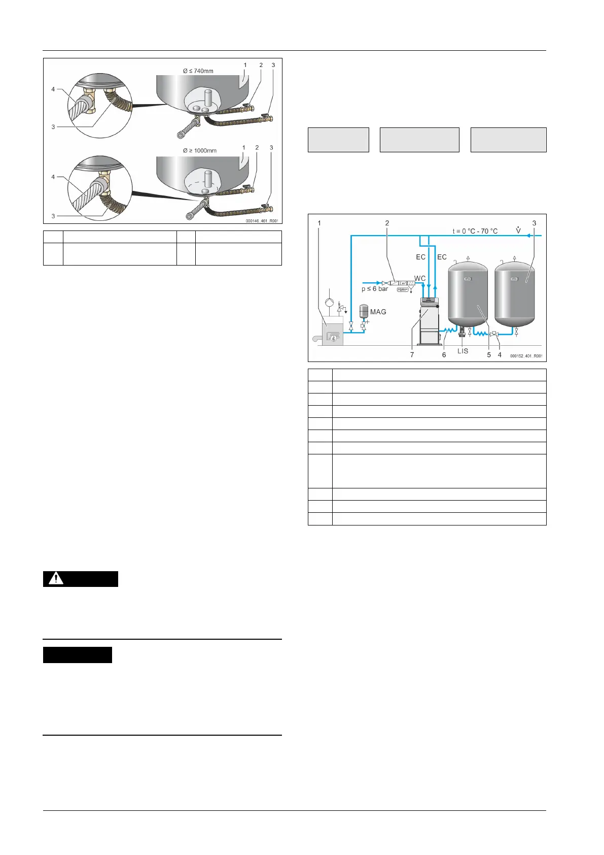
• Align the primary vessel, see chapter 7.3.1 "Positioning" on
page 11 .
• Connect the connection set (2) and (3) with the screw fittings and
gaskets to the connections at the lower vessel flange of the
primary vessel.
– Ensure that you connect the connection set for the overflow
collector to the connection (2) below the label (1). If you
interchange the connections, there is a risk that the pump
may run dry.
– For vessels up to 740 mm Ø:
• Connect the connection set (2) and (3) to the two free 1-
inch barrel nipples at the vessel flange.
• Connect the connection set (4) of the secondary vessel
to the T-joint at the outlet of the vessel flange.
– For vessels from 1000 mm Ø:
• Connect the connection set (2) to the 1-inch barrel
nipple of the vessel flange.
• Connect the connection sets (3) and (4) to the T-joint at
the 1-inch barrel nipple of the vessel flange.
Note!
If necessary, install the supplied connection set (4) at the
optional secondary vessel. Connect the connection set (4) with
a user-supplied flexible pipeline to the primary vessel.
7.3.4 Hydraulic connection
7.3.4.1 Connection to the facility system
Hot water vapour can cause burns to skin and eyes.
Hot steam can escape from the safety valve. The hot steam will
cause scalding of the skin and eyes.
• Ensure that the blow-off line of the safety valve is routed so
that injuries are not possible.
Damage due to improper installation
Additional device stresses may arise due to the connection of pipes
or system equipment.
• Ensure that pipes are connected from the device to the system
without them being stressed or strained.
• If necessary, provide support structures for the pipes or
equipment.
Connection to the primary tank
The control unit is positioned to the primary tank as determined by the
selected installation variant, and is connected to the tank using its
connection set.
The connections to the system are identified by adhesive labels on the
control unit:
Pump to
system
connection
Overflow valve to
system connection
Make-up to system
connection
Connection to the system
Optional equipment and accessories
Reflex rapid-action coupling R 1 x 1
Primary tank connection set
Typical representation of the control unit
Degassing line
• Gas-rich water from the system
• Degassed water to the system
If required, install a diaphragm expansion tank MAG ≥ 35 litres (Reflex
N, for example). It reduces the switching frequency and can be also
used in the individual protection of the heat generators. According to
DIN / EN 12828, the installation of valves between the device and the
heat generator is required for heating systems. Otherwise secure
locking mechanisms must be fitted.