Variomat Basic — 22.07.2020 - Rev.A
• The control unit is connected to the primary tank and the
secondary tanks, if provided.
• The water connections of the tanks to the facility system are
established.
• The tanks are not filled with water.
• The valves for emptying the tanks are open.
• The facility system is filled with water and gas-vented.
• The electrical connection has been created according to applicable
national and local regulations.
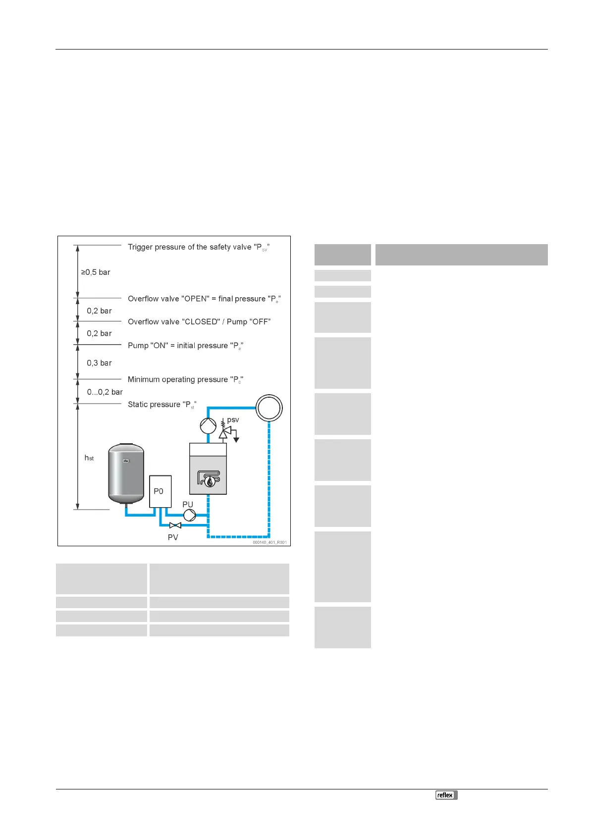
8.2 Variomat switching points
The "P
0
" minimum operating pressure is determined by the location of
the pressurisation. The controller calculates the switching points for the
solenoid valve "PV" and the pump "PU” from the "P
0
" minimum
operating pressure.
The "P
0
" minimum operating pressure is calculated as follows:
Enter the calculated value in the start
routine of the controller, see chapter 8.2
"Variomat switching points" on page 17 .
for safety temperatures ≤ 100 °C
for safety temperatures = 110 °C
*Addition of 0.2 bar recommended, no addition in extreme cases
Note!
Avoid dropping below the "P
0
"minimum operating pressure.
Vacuum, vaporisation and cavitation are thus excluded.
8.3 Modifying the controller's start routine
Note!
For handling the operator panel see chapter 10.1 "Operator
panel" on page 22
The start routine is used to set the required parameters for the device
commissioning. It commences with the first activation of the controller
and can be run only once. Parameter changes or checks are possible
after the start routine in the customer menu is exited, see chapter 10.2
"Configuring settings in the controller" on page 22 .
Note!
Plug in the contact plug to provide power (230 V) to the
controller.
You are now in Stop mode. The "Auto" LED on the operator panel has
extinguished.
Indication on
the display
Standard software in various languages.
Read the
operating
manual
Prior to commissioning, read the entire operating
manual and verify the proper assembly.
Enter the value for the minimum operating
pressure.
• Calculation of the minimum operating
pressure, see chapter 6 "Technical data" on
page 9 .
Change the flashing display items for "Hour",
"Minute", and "Seconds" to the current time.
• The time of an alarm will be stored in the fault
memory.
Change the flashing display items for "Day",
"Month", and "Year" to the current date.
• The date of an alarm will be stored in the fault
memory.
00500 l / 740
mm
GB = 0093 kg
Select the size of the "VG" primary tank.
• For the primary tank data, see the type plate
or, see chapter 7.3.6 "Fitting the level sensor"
on page 13 .
1 % / 1.7 bar
Null balancing!
Null balancing of the level sensor.
• The controller checks whether the level
measuring signal matches the dimensional
data of the "VG" primary tank. The primary
tank must be fully emptied, see, see
chapter 10.2 "Configuring settings in the
controller" on page 22 .
0 % / 1.0 bar
Null balancing
concluded
successfully!
Upon successful conclusion of the null balancing,
confirm with "OK" on the controller operator panel.