I/O module (optional expansion module)
Variomat Basic — 22.07.2020 - Rev.A
– Communication module for external operation of the
controller
– Master-Slave-Connect for master controllers for maximum 10
devices.
– Combined switching to increase capacity and parallel
switching of 2 hydraulically directly connected systems
– Bus modules:
• Profibus DP
• Ethernet
• Diaphragm rupture monitor.
Note!
Separate operating instructions are supplied with accessories.
5 I/O module (optional expansion module)
The I/O module is connected and wired in the factory.
It is used to expand the inputs and outputs of the Control Basic
controller.
The I/O module has two isolating amplifiers for analogue signals:
• Pressure measurement
• Level sensor
Six digital inputs and six digital outputs are used to process messages
and alarms:
Three inputs, N.C. with 24 V self potential for standard settings.
• External temperature monitoring
• Minimum pressure signal
• Manual make-up of water
Three inputs, N.O. with 230 V self potential for standard settings.
• Emergency-Off
• Manual operation (e.g. for pump or compressor)
• Manual operation for the overflow
Potential-free as changeover contacts. Default settings for messages:
• Make-up fault
• Below minimum pressure
• Above maximum pressure
• Manual or Stop operation
Note!
• For the default settings of the I/O modules, see
chapter 5.2.4 "I/O module default settings" on page 8
• All digital inputs and outputs can be set freely as option.
Settings to be made by Reflex Customer Service, see
chapter 13.1 "Reflex Customer Service" on page 27
5.1 Technical data
Permissible operating
temperature:
Permissible storage temperature:
230 V AC, 50 – 60 Hz (IEC 38)
• 6 floating relay outputs (changeover)
• 3 digital inputs 230 V AC
• 3 digital inputs 24 V AC
• 2 analogue outputs, to be set using jumpers
• 0 V – 1 V or 2 V – 10 V
• 0 mA – 20 mA or 4 mA – 20 mA
Interfaces to the controller
• RS-485
• 19.2 kbit/s
• Floating
• connection with plug or screw terminals
• RSI-specific protocol
5.2 Settings
Danger to life from electric shock!
Risk of serious injury or death due to electric shock. Some parts of
the main board may still be at a voltage of 230 V even after the
mains plug has been pulled out.
• Before you remove the covers, completely isolate the device
controller from the power supply.
• Verify that the main circuit board is voltage-free.
5.2.1 Terminator settings in RS-485 networks
Examples for the activation and deactivation of terminators in RS–485
networks.
• The main circuit board of the Control Basic provides either the DIP
switches 1 and 2 or the jumper J3.
• Maximum length for an RS–485 connection is 1000 metres
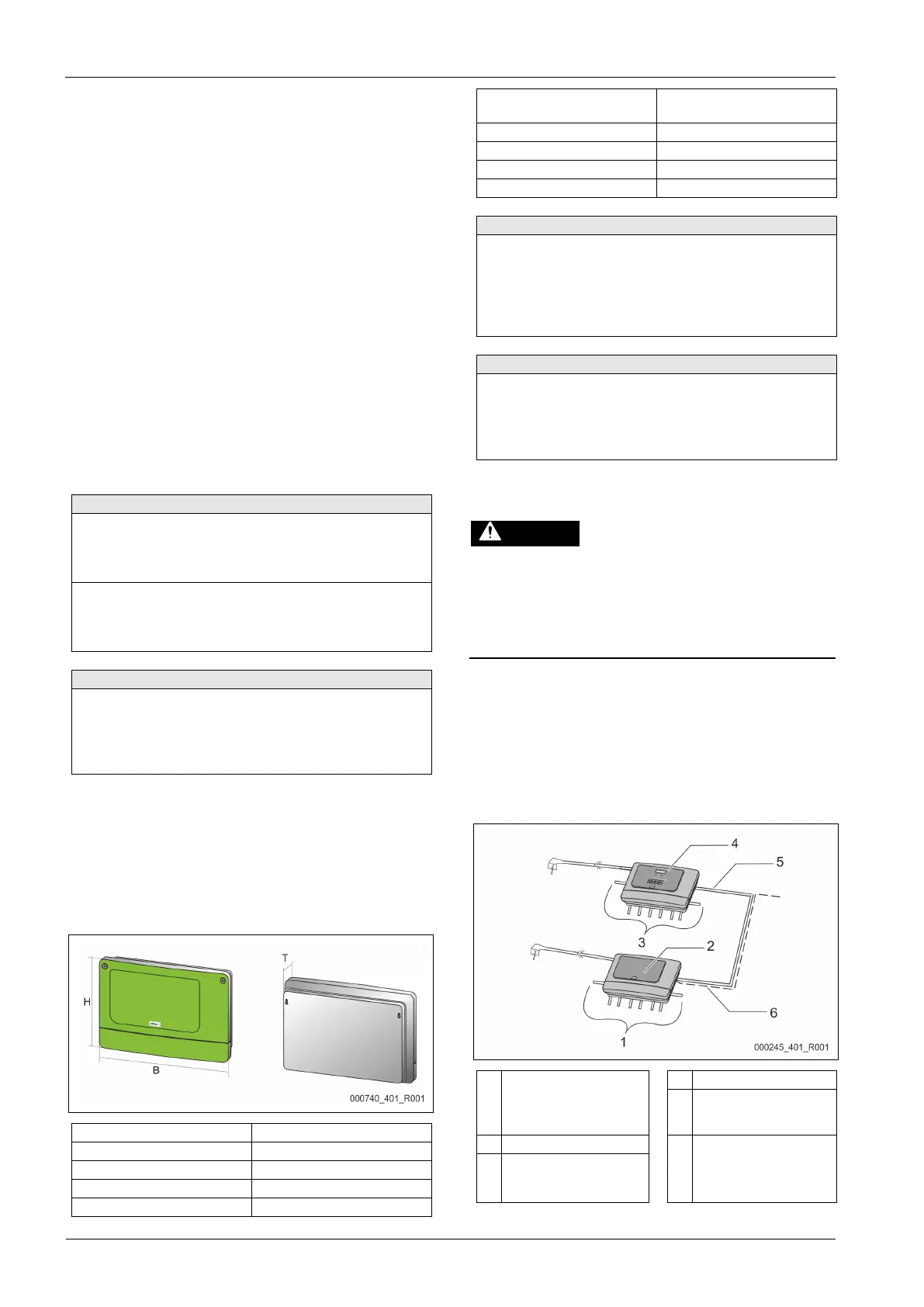
Device controller with I/O module
Relay outputs of the I/O
module
• 6 digital outputs
• 2 analogue outputs
"Control Basic" controller
Optional RS-485
connection
• Master - Slave
• Field bus
Connections of the I/ O
conductors