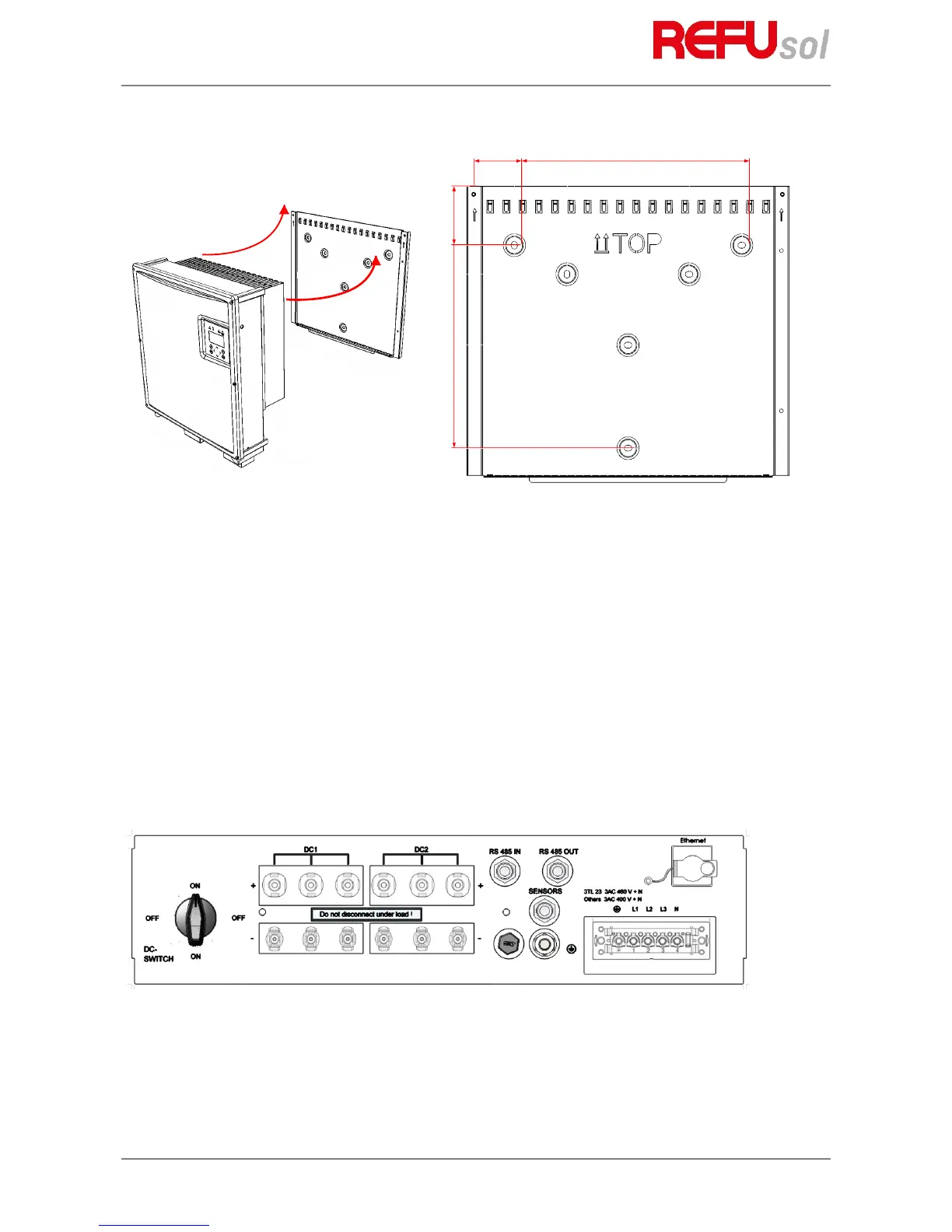
Fig. 7: Mounting the inverter
1. Use the wall bracket to mark the positions of the holes to be drilled.
2. Attach the mounting plate to the wall with the outer holes. The screws for attachment to the wall are
not included. Screws with a diameter of 6 mm must be used.
3. Push the cooling fins of the inverter into the tabs of the wall mounting plate. Push the inverter
upwards until it stops. Place the lower edge of the cooler onto the wall holder. Ensure that the rib
profile is locked behind the nuts.
4. Secure the inverter in these nuts using the enclosed screws (M5x20). As an alternative, you can also
use a padlock (shackle 4 mm in diameter) to protect the inverter against theft. The design of the wall
bracket ensures that the inverter is automatically centered in this bracket.
5. In order to avoid adhesive residue on the display, remove the display protection immediately after
installation.
61
4.7
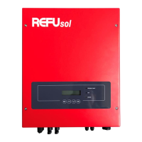
Device connectors
The following figure shows the connectors of the inverter on its bottom side.
Fig. 8: Device connectors REFUsol 08K ... 23K
The inverter is provided with the following connectors, as seen from left to right, top to bottom:
• 6 pair of PV generator connections
• RS485 connectors (IN and OUT)
• SENSOR (connection: Irradiation and temperature sensor, external shutdown signal)