24 REFUsol 08K ... 23K REFU Elektronik GmbH
4.11
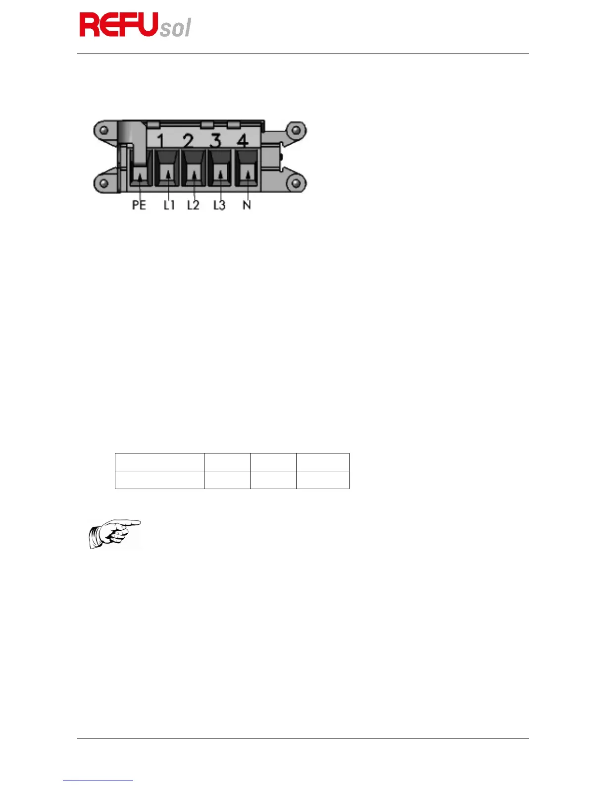
Power Supply Line
Fig. 10: Power Connection
Select the cross-section of the power supply line such that line losses are as low as possible. However,
observe the following points:
• the installer must select the cable material according to the operation mode (installation location and
laying type) and the national regulations.
• Due to the construction, the recommended feed line for all cross-sections is a fine wire.
• Copper wires must be used.
• Rigid wires are not recommended for the use of 16 mm
2
cables.
• The wires are to be installed in the correct position in order to minimise lateral forces on the net
connection. The lateral forces must not exceed 250 N.
• The seal is run through a hole in the screw (below the screw head of the adapter housing) and the opening
provided and attached to the housing of the device.
The following table shows the maximum wire lengths upon use of a REFUsol 08K ... 23K depending on the
cable cross section with a voltage drop below 1 %:
Line cross section 6.0 mm² 10.0 mm
2
16.0 mm
2
Max. line length 30 m 50 m 70 m
4.11.1
Fitting of supplied power plug
The cable fitting of the standard connector housing supplied allows 5 x 6 mm² to 5 x 16 mm² cables to be
connected. The maximum outside diameter of the power supply line may be 30.3 mm (e.g. Lapptherm 145, 5
x 6 mm²).
1. Bend cable into position.
2. Strip the cable as shown in the illustration.
Note:
In order to ensure IP65 protection, the AC connection housing supplied must
be used.