12 ST 1, STR 1
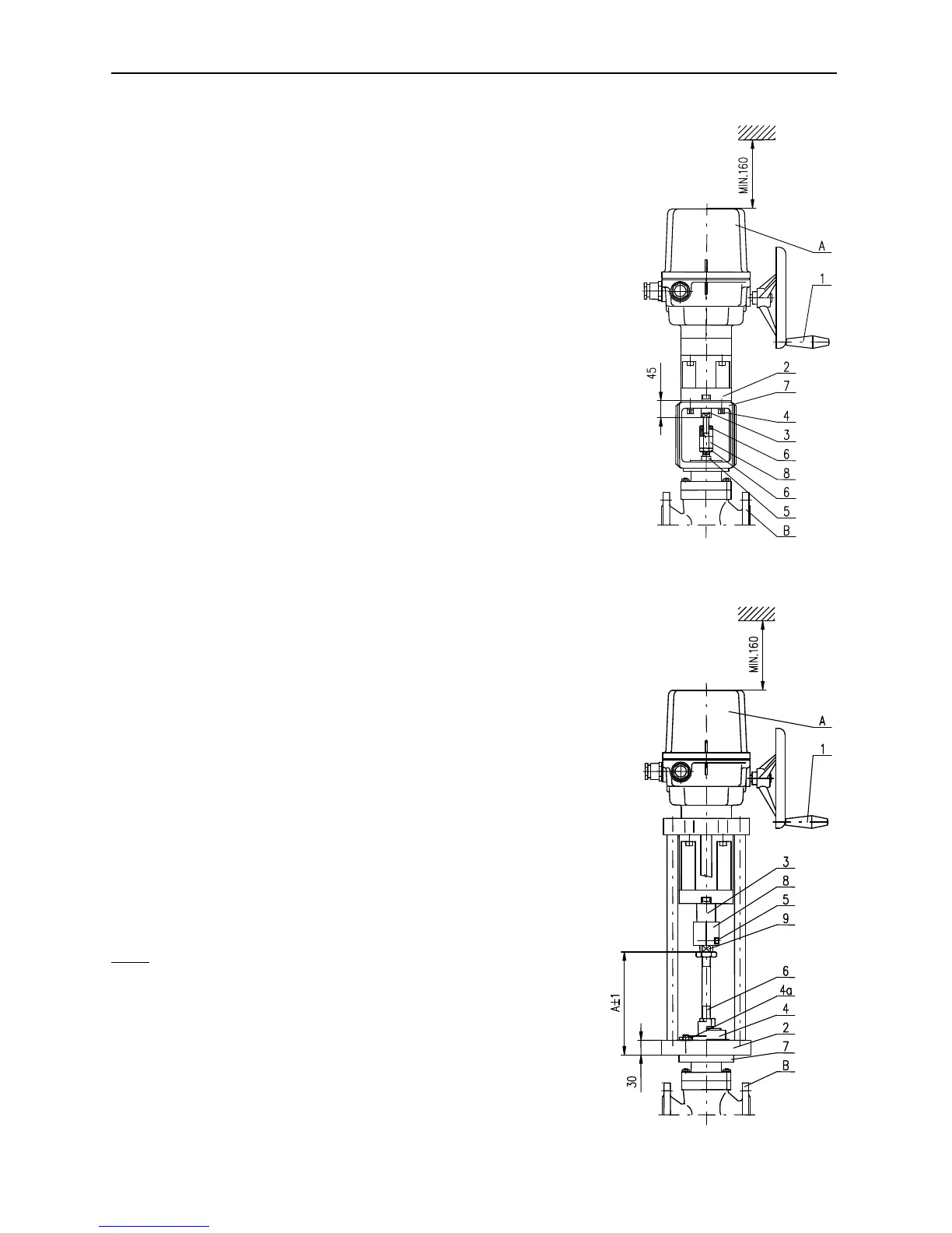
Mechanical connection with connection dimensions according to DIN
• Properly defat contact surfaces of the EA connecting flange and the valve.
• Check the nameplates to assure that actuator and valve strokes are the
same.
• Set the actuator (A) and the valve (B) to the position ”closed“.
• Put the actuator (A) onto the valve (B) to have the actuator shaft (3) leant
onto the valve coupling (8).
• Turn the valve output shaft (5) to connect the stem with the valve output shaft
having the actuator flange (2) sitting on the valve flange (7).
• Tighten the screws (4) with the cross system to connect the actuator flange
(2) with the valve flange (7).
• Check connection dimensions in accordance with Fig. 1.
• Turn the valve output shaft (5) by one revolution and lock it with the nut (6)
(to create pre-stressing against the valve seat).
A ... electric actuator
1 ... hand wheel
2 ... actuator flange
3 ... shaft
4 ... screw
B ... valve
5 ... valve output shaft
6 ... locking nut
7 ... valve flange
8 ... valve coupling
Fig. 1
Mechanical connection for pillar versions with flanges of A, B, C and D types
• Set the actuator (A) and the valve (B) to the position ”closed“.
• Loosen and unscrew two screws (5) on the actuator shaft (3) and
disconnect the coupling clamping parts (8)
• Screw the coupling nut (8) onto the valve output shaft (6) (max. 28mm)
to have an allowance between the coupling nut (9) and the actuator
shaft (3) after the actuator is sat on.
• Place the actuator (A) onto the valve (B) and fix the actuator slightly
with the screws (4a), or with the central nut (4) (according to shape of
connecting flange of EA) in the way you be able to move it.
• By turning hand wheel (1) move end shaft EA (3) toward thread
coupling (8) screwed onto valve output shaft (6) (or unscrew thread
coupling)
• Put the clamping parts of the thread coupling (8) on, and tighten the
both coupling screws (5) to have the coupling nut able to rotate
• Tighten the screws (4a), or central nut (4) with the cross system to
fasten the actuator (2) and valve (7) flanges.
• Check the connection diameters in accordance with the Fig. 2.
• Unscrew the coupling nut (8) by one more revolution (to create the pre-
stress against the valve seat), and tighten the coupling screws (5) firmly
Notes:
1. Minimum mechanical ruggedness of screws is 8G.
2. If adjustment of the position-signalling unit or the transmitter in the production
plant do not correspond with the EA connected this way, adjust the units.
• In the end of mechanical connection check correctness of the
connection with the valve with rotating the hand wheel.
A ....... electric actuator
1 ....... hand wheel
2 ....... actuator flange
3 ....... shaft
4 ....... central nut
4a...... screw
5 ....... screw
B ... valve
6 ....... valve output shaft
7 ....... valve flange
8 ....... coupling