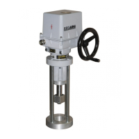
ST 1, STR 1 11
Supply voltage: ...................terminal 61 (L1) -1(N).....................230 V AC, ±10%
Frequency: ..........................50/60 Hz ±2%
Input control signals - analogue: ...........0 - 20 mA
.............................................................4 - 20 mA
.............................................................0 - 10 V
Input resistance for signal 0/4 - 20 mA.........................................................................................................250Ω
Input resistance for signal 0/2 - 10 V........................................................................................................... 50kΩ
(Actuator opens at rising of control signal.)
Controller linearity: .......................................0.5 %
Controller insensitiveness: .........................1 - 10% (adjustable)
Feedback (position transmitter): .................resistive 100 up to 10,000 Ω
current 4 up to 20 mA
Power outputs: ............. 2x relay 5A/250 V AC
Digital outputs: ............4x LED (supply, error, adjustment, "opening", "closing" - with two-colour LED)
Error status: ...................................control switch 24 V, 2W - POR
Reaction at error situation: ...........transmitter error - error message LED
Control signal missing: .................error message LED
SYS mode: ......................................error message LED
Adjusters: .......................................communication connector
2x calibrating and adjusting button
Manual control: with hand wheel; rotating clockwisely (counterclockwisely) EA output part is moving
in direction "Z" - closed ("O" - open)
Mechanical connection: Basic and connecting dimensions are given in dimensional drawings.
Electric connection
with terminal board (X): - max. 24 terminals – connecting cable size max. 1,5 mm
2
- 3 cable bushings – 1xM12 - cable diameter from 3,5 to 5 mm, 1xM16- cable
diameter from 6 to 10,5 and 1xM20 - cable diameter from 8 to 14,5 mm
with connector (XC): - max. 32 terminals – connecting cable size max. 0,5 mm
2
- 2 cable glands, cable diameter 1x M20 - cable diameter from 8 to 14,5mm and 1xM25 -
cable diameter from 12,5 to 19 mm
with protection terminal: - external and internal, mutually connected and marked with protection
earthling mark.
Electric connection - according to wiring diagrams.
3. Installation and dismantling of actuator
3.1 Installation
Abide by safety measures!
Note:
Check again if placement of EA reply to chapter "Operation conditions". In case that operation conditions
are different from recommended, consultation with producer is needed.
Before starting of mounting the EA onto the valve:
• Check again whether the EA was not damaged during storing.
• Check whether the adjusted operation stroke and connecting dimensions of the actuator (see the nameplate)
are in compliance with the valve parameters.
• In case of inconsonance, perform adjusting according to the part "Adjustment“.
3.1.1 Mechanical connection
EA is by the producer adjusted to parameters according to the nameplate, with connecting
dimensions according to the corresponding dimensional drawing and put it to a mid-position.
Before installation put the hand wheel on.
!

 Loading...