ST 1, STR 1 15
4. Adjusting of actuator
Abide by safety measures!
After mechanical connection, electrical
connection and checking of connection and
function start setting and adjustment of the
device. The adjustment can be performed at a
mechanically and electrically connected EA.
This part describes adjustment of EA to
specified parameters in case that any unit of
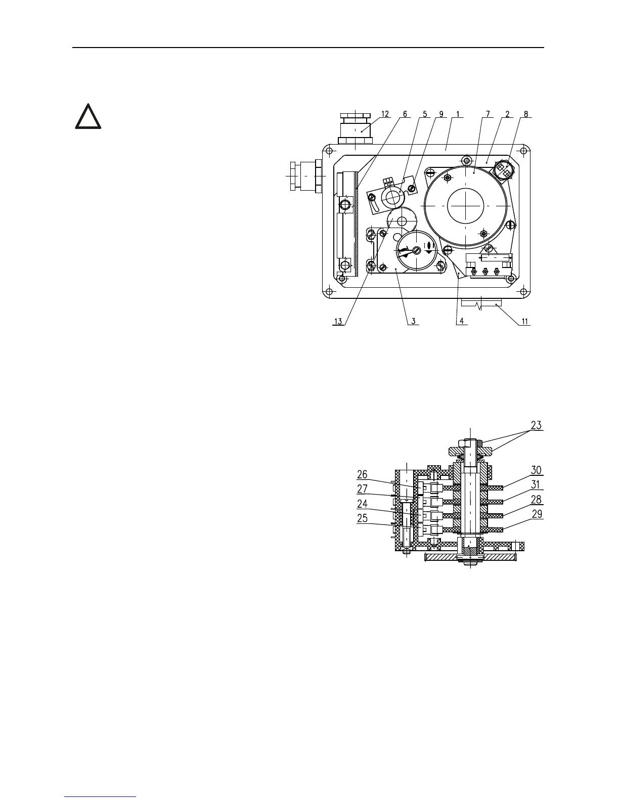
EA is reset. Laying of adjusters of the control
board is shown on Fig. 3
4.1 Gear unit adjustment
In the production plant switching-off
thrust for both the "opening" direction (the
thrust switch S1) as well as for the "closing"
direction (the thrust switch S2) are adjusted to
specified value ±10%. If not agreed else they
are adjusted to maximum value.
Adjustment and setting of the gear unit to other values without any testing device for thrust measuring is
not possible.
4.2 Adjustment of position-indicating unit (Fig.4)
The EA are in the production plant adjusted to a fixed
angle (according to the specification), given on the nameplate.
While setting, adjusting and resetting follow these steps (Fig. 4):
• In the version with a transmitter put the transmitter out of
mesh.
• Loosen the nuts (23) fixing cams still having the Belleville
spring creating axial pressure.
• Put the EA to the position "open" and turn the cam (29)
clockwisely until the switch S3 (25) switches.
• Change setting of the EA by the angle, where the position
"open" is to be indicated and turn the cam (31) clockwisely
until the switch S5 (27) switches.
• Put the EA to the position "closed" and turn the cam (28)
counterclockwisely until the switch S4 (24) switches.
• Turn the EA back by the angle, where the position "closed" is
to be indicated and turn the cam (30) counterclockwisely until the switch S6 (26) switches.
• Having the EA adjusted lock the cams with the central milled nut and counter-nut (23).
If not agreed else the signalling cams are set next to the limit positions. The signal possibility is available
along the whole operation angle in both directions, i.e. 100%.
!
Fig. 4