18 ST 1, STR 1
4.5 Adjustment of the Capacitive Transmitter CPT1/A (Fig.8)
The chapter describes adjustment of the capacitive transmitter to the specified parameters (standard
values of output signals) in case they are reset. The capacitive transmitter serves as a position transmitter of
electric actuators with unified output signal of 4÷20 mA in electric actuators ST, or as a feedback of a position
controller, or if required it functions also as a remote position transmitter of electric actuators with unified output
signal of 4÷20 mA in electric actuators STR with controllers.
Note:
In case that reversed output signals are needed (in the position ”OPEN” minimum output signal) contact
personnel of service centres.
The capacitive transmitter CPT1/A is adjusted by the producer to the fixed operation stroke according to
the order and wired according to the wiring diagrams placed into the cover. Check the power supply of the user
after connecting to terminal of the terminal board before the transmitter is electrically checked. Adjustment of the
capacitive transmitter can be performed when the position switches are adjusted. The adjustment is performed
with the power supply of 230 V/50 Hz and ambient temperature of 20±5°C.
The following versions of electric actuators with built capacitive transmitters can be specified :
A) The version without any power supply (2-wire version) for EA ST
B) The version with a power supply (2-wire version) for EA ST
C) The version CPT as a feedback to the position controller for EA STR with controllers
A.) Adjustment of the Capacitive Transmitter without any Power Supply
Before connecting check the power supply. The measured voltage should be in range from 18 up to 28 V DC.
The voltage of the power supply must not be in any case higher than 30 V DC. The transmitter can be
irreversibly damaged
While checking or adjusting the output signal of 4÷20 mA follow these steps:
• Connect a mA meter of precision class 0,5 and loading resistance lower than
500Ω serially with the transmitter (pole „-„; terminal 82)
• Put the actuator to the position ”CLOSED“, the signal value should decrease.
• Check the signal value for the position ”CLOSED“ (4 mA).
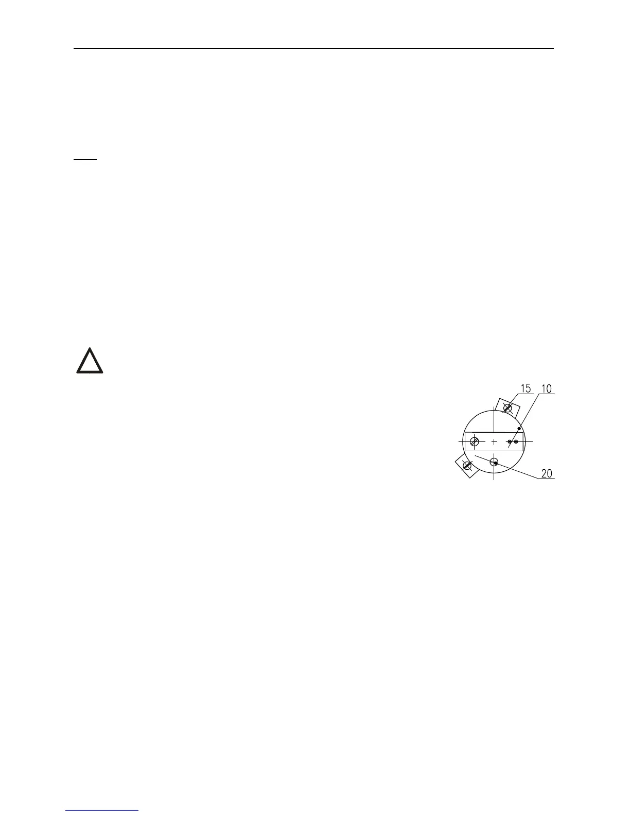
• Tune the signal with loosening the fixing screws (15) and turning the trimmer (10)
until the required value of 4 mA is reached. Tighten the fixing screws.
• Put the actuator to the position ”OPEN“, the signal value should raise.
• Check the signal value for the position ”OPEN“ (20 mA).
• Tune the signal with turning the trimmer (20) until the required value of 20 mA is
reached.
• Check the signal value for the position ”CLOSED“ and then for the position ”OPEN“.
• Repeat the procedure until the change from 4 to 20 mA is reached with deviation less then 0,5 %.
• Disconnect the meter and lock the screws with a varnish.
B.) Adjustment of the Capacitive Transmitter with the Power Supply:
1.) Check the power supply: 230 V AC ±10% on the terminals 78,79
2.) While checking or adjusting the output signal of 4÷20 mA follow these steps:
• Connect a mA meter of precision class 0,5 and loading resistance lower than 500Ω on the terminals 81,82.
• Follow the procedure described in the previous chapter A.
C.) Adjustment of the Capacitive Transmitter Served as a Feedback of the Position Controller
While checking or adjusting the output signal of 4÷20 mA follow these steps:
• Disconnect the circuit on the terminals 81 and 82 removing the jumper.
• Connect power supply to the terminals 1 and 61.
• Disconnect the control signal from the terminals 86 and 88.
• Put the actuator to the direction ”OPENING“ or ”CLOSING“ with the hand wheel or connecting power supply
to the terminals 1 and 200 for the direction ”OPENING“, or 1 and 24 for the direction ”CLOSING“.
• Connect a mA meter of precision class 0,5 (e.g. digital) and loading resistance lower than 500Ω on the
terminals 81,82.
• Follow the procedure for the version without any power supply described in the previous chapter A.
• Having the transmitter adjusted put the jumper again on the terminals 81 and 82 in case that the
output signal wont be used (the circuit through the terminals 81 and 82 should be closed).
!
Fig. 8