ST 1, STR 1 19
• Connect the control signal to the terminals 86 and 88
The user has to arrange grounding of the 2-wire circuit of the capacitive transmitter to the electrical
ground of a joined controller, computer, etc. The grounding should be performed only in one place in
any part of the circuit outside the electric actuator!
Note:
The trimmer (20) can be used to adjust the output signal of the capacitive transmitter to any value of operation
stroke in range from ca 40% up to 100% of the value of the operation stroke adjusted by the producer and stated
on the actuator′s nameplate.
4.6 Adjustment of position controller (Fig. 9)
The built-in position controller REGADA of new generation is a user-friendly control system to control
actuators with an analogue signal. The controller takes advantages of high-power RISC processor
MICROCHIP to perform all functions. It provides also continuous automotive diagnostics of the system,
error messages as well as number of relay switching and number of controller's operation hours. Placing an
analogue signal onto the input terminals of the terminal board 86/87 (GND, -) and 88 (+) causes that the EA
output is reset.
Required parameters and functions can be programmed using function buttons SW1 - SW2 and LED
diodes D3 - D4 placed directly on the controller, see Table 2.
4.6.1 Setting of controller
The controller's microprocessor unit is in the production plant programmed to parameters given in
Table 2 (Note 2).
Setting of the controller is performed using buttons and LED diodes. Adjust the position and thrust
switches and the position transmitter before adjustment of the controller.
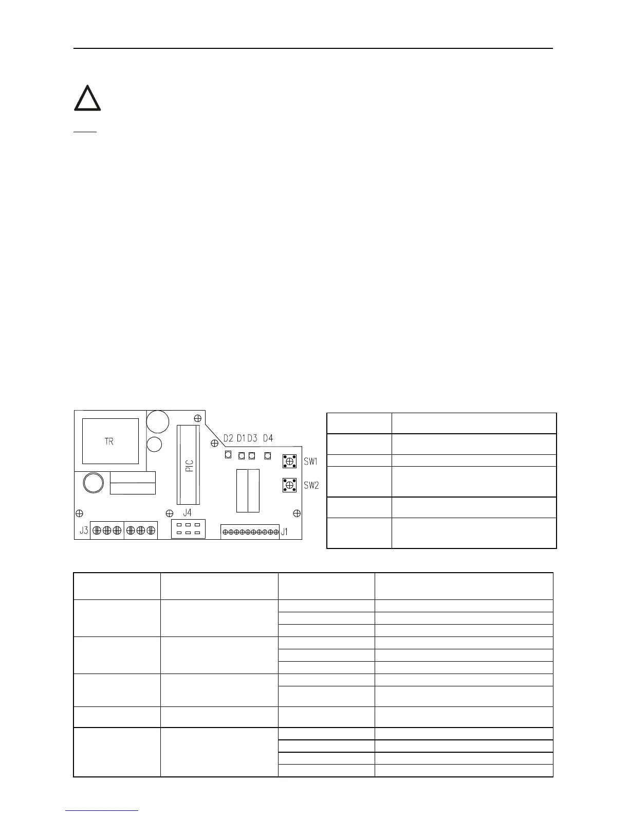
Laying of adjusters and signalling elements on the board of the REGADA controller is shown on Fig.9:
Fig. 9
Table 2
D3 (yellow) diode
number of blinking
Adjust menu
D4 (red) diode
number of blinking
Adjusted parameter
1 blink 0-20mA
2 blinks
4-20 mA (*) (**)
1 blink control signal
3 blinks 0-10V DC
1 blink EA opens receiving signal SYS
2 blinks EA closes receiving signal SYS
2 blinks
response for signal
SYS-TEST
3 blinks
EA stops receiving signal SYS (*)
1 blink EA CLOSING at increasing of control signal
3 blinks
mirroring
(ascending/descending
characteristics)
2 blinks
EA OPENING at increasing of control
signal (*)
4 blinks insensitiveness of controller 1 to 10 blinks
insensitiveness of controller of 1-10%
(3% set by the producer) (*)
1 blink narrow thrust
2 blinks
narrow position (*)
3 blinks wide thrust
5 blinks way of regulation
4 blinks wide position
SW1 button
starts an initialisation routine an allows
listing in the adjust menus
SW2 button
setting of parameters in the chosen
menu
D1 diode
power on indication
D2 diode
motion to the direction "opening"
indication (green) - "closing" (red)
indication
D3 diode
(yellow light) number of blinking codes
indicates chosen adjust menu
D4 diode
(red light) number of blinking codes
indicates adjusted parameter of the
controller from the chosen menu
!