22 ST 1, STR 1
After every potential flooding of the product check, whether there is no water inside. After eventual water
penetration, dry the product before repeated putting into operation and replace damaged sealings, resp. other
parts of EA. identically check also tightness of cable bushings and replace them, if they are damaged.
• Every six months it is recommended to perform one check move in frame of adjusted operation stroke to
verify reliability of functioning with setting back to the original position.
• If the audit rules do not determine else the inspection of EA is performed ones a year and tightening of all
connecting and grounded screws have to be checked to avoid overheating.
• After 6 months from putting of EA into operation and once a year it is recommended to check tightening of
fixing screws between the EA and the valve. (Tighten the screws with the cross system.)
• While connecting and disconnecting of the EA check the tightness of cable glands – those with
damaged sealings should be replaced by new ones of the approved type!
• Keep the EA clean and take care about removing impurities and dust. The cleaning has to be
performed regularly according to the operation possibilities and requirements.
5.3 Troubleshooting
At failure of power supply the EA stops in the position where it was before the failure. If needed the EA
can be set only with the manual control (the hand wheel). After restoration of power the EA is prepared for
operation.
In case of failure of any element of the EA it can be changed by a new one. Entrust the change to a
service centre.
In case of an EA failure, which cannot be eliminated directly in operation, follow instructions for under-
guaranty and after-guaranty service. For controller repair a F1,6 A subminiature fuse for PCB should be used,
alternativelly also F 2A, 250 V e.g. Siba type 164 050.1,6 or MSF 250, and for DB .... voltage source repair a
M160 mA, 250V fuse, e.g. Siba, or MSF 250.
Note: If the EA requires dismantling follow the chapter "Dismantling".
Taking the EA to pieces for repair purposes is allowed only by professionally qualified persons
trained in the production plant or by a contracted service centre!
6. Accessories and spare parts
6.1 Accesories
The EA is delivered with the hand wheel.
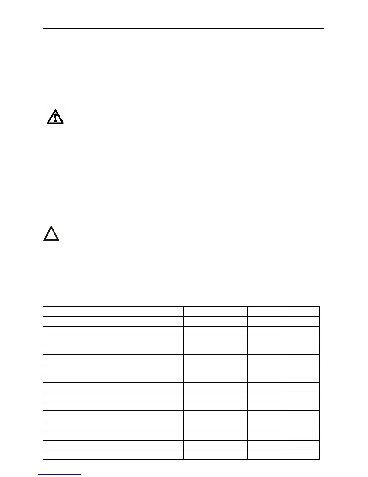
6.2 Spare parts list
Spare part Order Nr. Position Figure
Electric motor; 15W/39 VA; 230V AC 63 592 311,63592306 7 3
Electric motor; 15W/40 VA; 3x400V AC 63 592 332 7 3
Electric motor; 20W/40 ; 24V AC/DC 63 592 289 7 3
Micro-switch CHERRY DB6G-B1RB 64 051 220 3,4 3
Resistant wire transmitter (potentiometer) 1x100Ω 64 051 812 5 3
Resistant wire transmitter (potentiometer) 2x100Ω 64 051 814 5 3
Resistant wire transmitter (potentiometer) 1x2000Ω 64 051 827 5 3
Resistant wire transmitter (potentiometer) 2x2000Ω 64 051 825 5 3
Capacitive transmitter 64 051 499 10 8
Sealing ST 1 04 709 000 - -
Sealing STR 1 62 732 376 1 -
Cable glands M12 63 456 579 12 3
Cable glands M16 63 456 595 12 3
Cable glands M20 63 456 596 12 3
Terminal board EKL 63 456 710 6 3
!