16 ST 1, STR 1
4.3 Adjustment of resistant transmitter (Fig. 5)
The resistant transmitter is in the EA ST 1 used to function as a remote position indicator; in the EA STR
1 with controller to function as a feedback in the position controller and if needed also in the position of a
remote resistant position indicator. Before the resistant transmitter adjustment the position switches have to be
adjusted. Adjustment consists in setting of the resistance in the defined limit position of the EA.
Notes:
In case that the EA is not used in the whole stroke range given on the nameplate, the resistance in the limit
position "open" is proportionally reduced.
In the EA STR 1 with controller 2000Ω resistant transmitters are used. In the other cases if the resistant branch
is lead to the terminal board the resistance of the transmitters is according to the customer's specification.
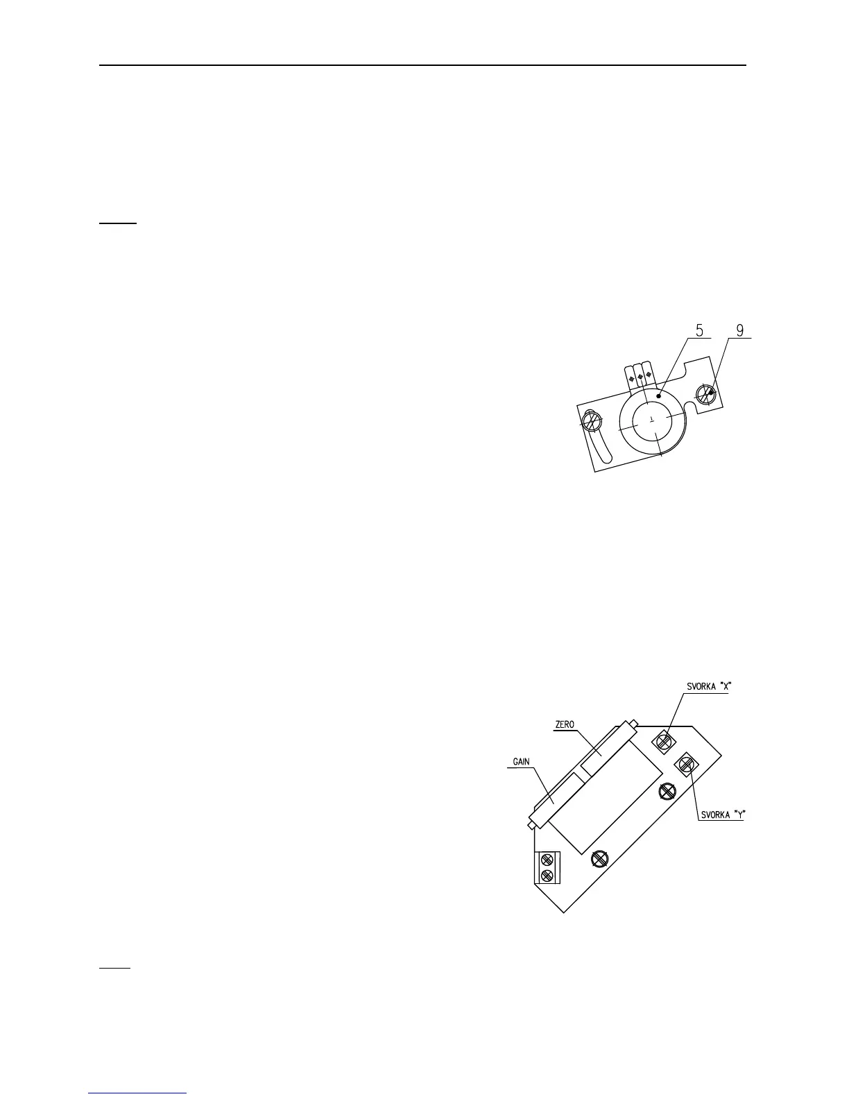
To adjust the transmitter follow these steps:
• Loosen the fixing screws (9) of the transmitter holder and push the
transmitter out of mesh.
• Connect a meter for resistance measuring to the terminals 71 and 73 of the
EA ST 1 terminal board, or to the terminals 6 and 7 of the EA STR 1 with
controller terminal board.
• Put the actuator to the position "closed“ (with the hand wheel, or with the
local electric position control until the corresponding position switch S2 or
S4 switches).
• Rotate the transmitter shaft until resistance of ≤5% of the nominal
transmitter resistance can be read on the meter in case of EA ST 1, or 3 up
to 7% of the nominal transmitter resistance in case of EA STR 1, or in case
of EA ST 1 with EPV, i.e. with the resistant transmitter with the converter PTK1
• In the position put the transmitter to mesh with the drive wheel and fix the fixing screws on the transmitter
holder.
• Disconnect the meter from the terminal board.
4.4 Adjustment of the Electronic Position Transmitter (EPV) - the Resistive
Transmitter (Potentiometer) with the Converter PTK 1
4.4.1 EPV – the 2-wire version (Fig. 6)
The position transmitter with the converter PTK1 is in the plant adjusted to have the output current signal
on the terminals 81-82 as follows:
• in the position „open“ ........................................ 20 mA
• in the position „closed“ ..................................... 4 mA
If the transmitter requires a new adjustment follow these steps:
Adjustment of the EPV in EA ST:
• Put the actuator to the position „closed“ and switch the power
supply off.
• Adjust the resistive transmitter according to the previous
chapter. The resistance is to be metered on the terminals X-Y
(Fig. 6). The used transmitter resistance is 100 Ω.
• Switch the converter′s power supply on.
• Turn the adjusting trimmer ZERO (Fig. 6) to adjust the output
current signal rate measured on the terminals 81-82 to 4mA.
• Set the actuator to the position „open“.
• Turn the adjusting trimmer GAIN (Fig. 6) to adjust the output
current signal rate measured on the terminals 81-82 to 20mA.
• Check the output signal of the converter in the both limit positions, and repeat the procedure if needed.
Note:
The output signal of 4-20mA can be adjusted at the range from 75 up to 100% of the rated stroke stated on the
actuator′s nameplate. At values less than 75% the value 20mA is reduced proportionally.
Fig.5
Fig. 6