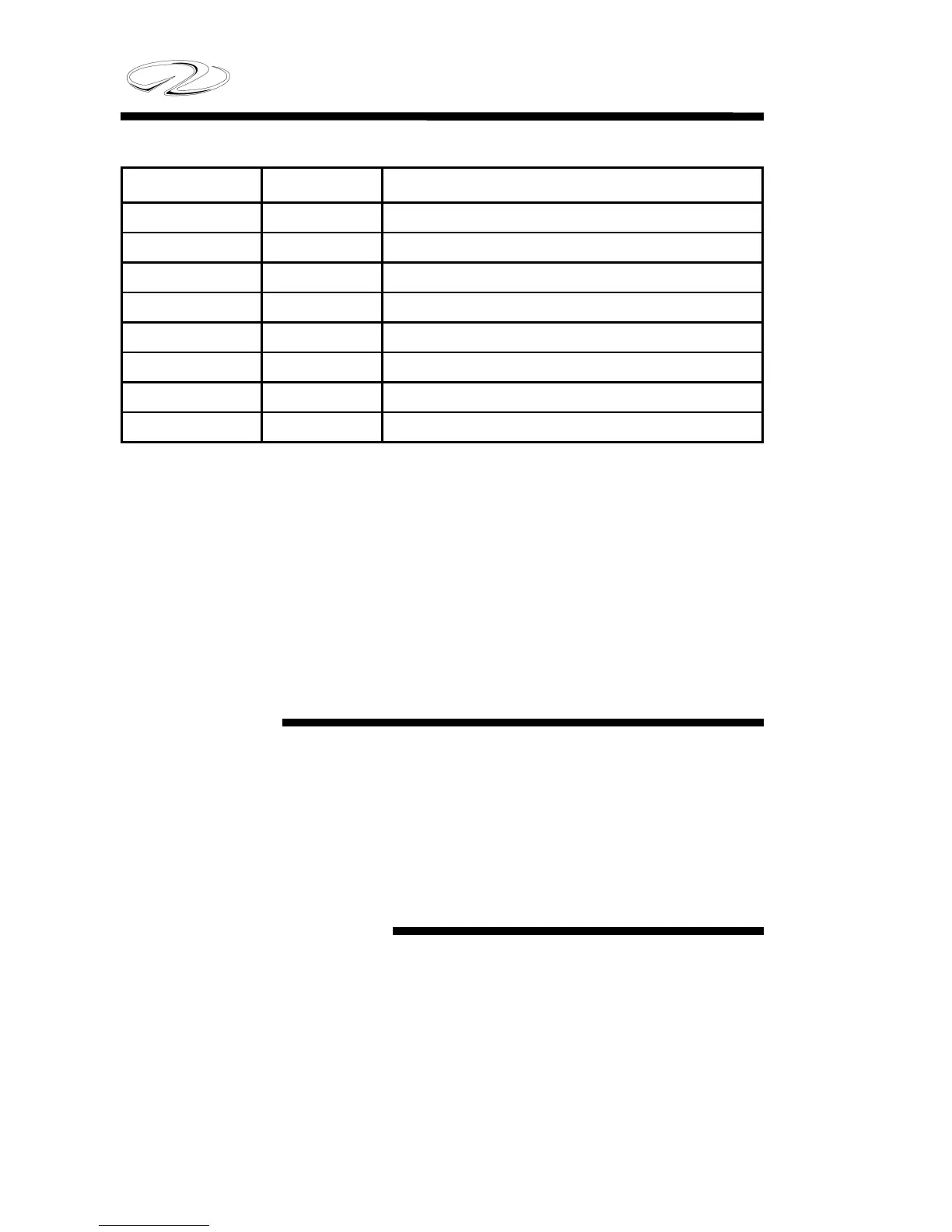
COLOR GAUGE FUNCTION
Red 2 / 0 Main DC Panel Feed
Red 00 Battery Cable To Engine
Red / Black 16 Windlass Up
Red / White 16 Windlass Down
Yellow 12 Blower
Yellow / Black 16 Stereo Memory
Yellow / Black 16 Track Monitor
Yellow / Red 14 Engine Cranking Circuit
The standard wire color, gauge size, and function shown is used
throughout the marine industry. The chart is helpful in identifying wire
circuitry during troubleshooting or the adding or marine accessories.
NEVER replace a wire with a size other than shown in the chart.
This practice could result in fi re or component failure. Contact your
Regal dealer for replacement wires and harnesses.
DC Switches
Switches located at the helm are part of your DC circuitry. Switches
are in essence a break in the circuit from the battery to your electrical
components. When the switch is turned on, a red light shows
activation. See chapter 3.
DC Circuit Protection
As part of the direct current circuitry, depending on the make and
model engine you chose, will have either in line fuses or a fuse box for
its electrical components. These fuses protect the engine wiring from
overloads. Refer to the engine manufacturer’s manual for the fuse
locations, sizes, and operations.
4-6
Chapter 4