9
Systems
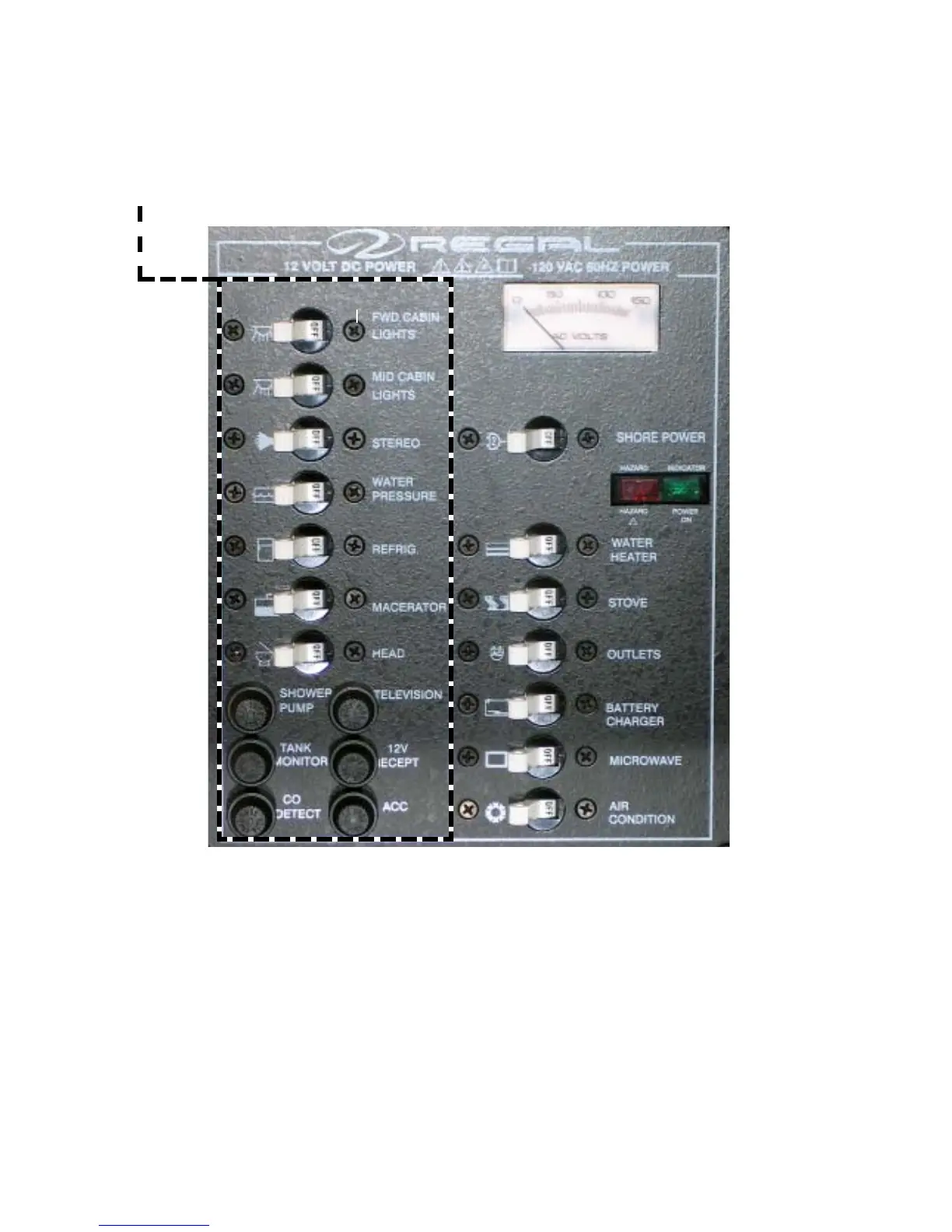
MAIN D.C.PANEL (TYPICAL) SWITCH FUNCTIONS
Typical D.C. Switches
The D.C. switches control various equipment functions
on the vessel. By activating each switch you will be able
to determine its corresponding shore power breaker.
Upon leaving the vessel turn all switches and breakers to
the “off ” position. If a breaker “pops” due to an overload
it will assume a “middle of the road” position until the
thermocouple cools down and it can be reset. Always
determine the cause of an overload and repair the problem
before trying to reset the breaker.
D.C. Line Voltage
The D.C. line voltage indicates current battery voltage.
Normal readings should be above 12 volts although it is
not abnormal for the meter to fluxuate somewhat. As D.C.
equipment is activated the volt meter will indicate a slight
change in meter readings. With the battery switches in the
off position upon leaving the vessel the meter will not
indicate any voltage. This is normal.
DC EQUIPMENT BREAKERS/SWITCHES
15
BKR. AMPERAGE
10
15
15
10
30
10
5
2.5
2.5
10
15
15