53
Systems
REMOTE
INSTRUMENT
PANEL
AC BREAKER
GEN-SET
ENGINE
BREAKER
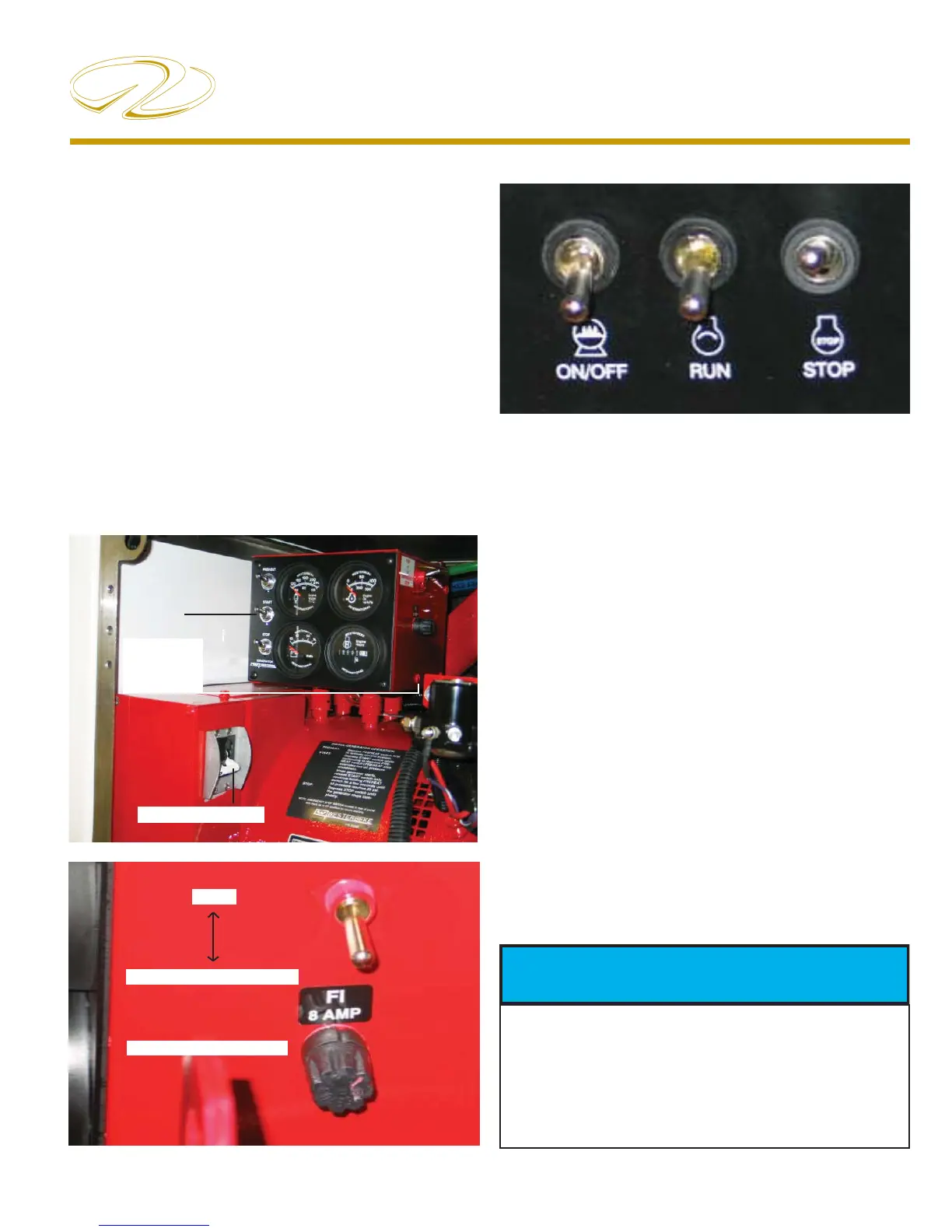
TYPICAL GEN-SET SWITCH CLUSTER- MAIN PANEL
Note the illustrations showing the remote instrument and
start panel. As part of the generator electrical system an
8 amp fuse protects the remote instrument panel wiring
circuit. See illustration B.
Above the fuse is a switch. This switch must be in the
“run” position or the generator will not start. The emer-
gency stop switch shuts the fuel off to both the remote
and ship’s main control panel and is normally for mainte-
nance purposes. See illustration B.
A 20 amp DC manual reset breaker protects excessive cur-
rent draw or electrical overload anywhere in the generator
engine wiring. Should this breaker trip the generator will
shut down. Reset the breaker only after the cause of the
problem has been determined. See illustration A.
An AC breaker will automatically disconnect any genera-
tor AC power from reaching the main ship’s control panel
in case of an electrical overload. It can be manually shut
off when performing generator maintenance to ensure
no AC power is coming out of the generator. See illustra-
tion A.
ILLUSTRATION A
Typical Electrical System
The generator starting system uses the port cranking
battery. The generator is normally started at the 12 volt
ship’s control panel located in the salon but it can also be
started using the remote instrument panel located at the
generator itself as needed. The latter is especially useful
while maintenance is being conducted. The generator
remote instrument panel features temperature, oil, DC
volts, hour meter gauges and pre-heat, start and stop
switches. The starting switches can be reached through an
access panel at the sound shield.
One of the switches is set up different on the ship’s main
control panel. Here the pre-heat switch is called an “on”
switch. The start and stop switches by name and function
are identical to the switches on the remote panel.
INST. PANEL FUSE
EMERGENCY STOP
RUN
ILLUSTRATION B
TO PREVENT POSSIBLE GENERATOR
DAMAGE ALL SHORE POWER
BREAKERS AND AC SWITCHES
NEED TO BE DEACTIVATED BEFORE
STARTING OR STOPPING GENERATOR.
 Loading...