46 | LRI4E / HRI4E Direct Vent Gas Insert
|
46
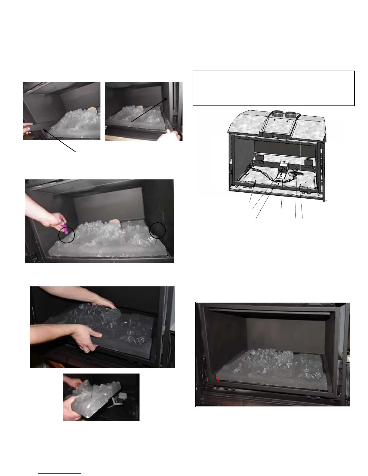
maintenance
LRI4E CERAMIC BURNER REMOVAL / INSTALLATION
3) Lift the Burner slightly while pulling forward to clear the mixing tube.
4) To install - reverse Steps 3-2, see Step 1 for correct installation tips.
1) Remove left/right ller sections - see below.
Discard llers only if inner panels are being installed.
2) Remove burner by removing left and right screws o the burner bracket.
Left /right ller sections.
Burner Mountin
Bracket Right
Burner Mounting
Bracket Left
Mixing Tube
Support
Gas Orfice
Pilot Assembly
Air
Shutter
Firebox
Front View
Care must be taken when installing the burner into the rebox.
Do not damage, knock or scrape the pilot assembly.
The ame sensor and ignition lead are fragile and can be damaged
easily.
*Satin black paint is included if touch ups are required.
Important Note:
A correctly installed burner - the burner is back far enough,
lower the front edge so that the front ange of the burner
(underneath) sits down into the grooves in the burner mount-
ing brackets Left and Right. There will be a small gap between
the Ceramic Burner and the rebox Bottom Flange. The Burner
should be situated about ¼” (6mm) inside the front edge of the
rebox.
INSTALLATION
REMOVAL
6mm