EasyManuals Logo

Regin Regio Midi User Manual

Regin Regio Midi
90 pages
To Next Page IconTo Next Page
To Previous Page IconTo Previous Page
Page #21 background imageLoading...
Page #21 background image
Regio Midi manual Chapter 6 Installation 21
Wiring for model for CO
2
control (RC-C3DOC)
Figure 10. Connection diagrams for model for CO
2
control
Terminal
Designation
Operation
10
G
Supply voltage 24 V AC
11
G0
Supply voltage 0 V
12-14
No function.
20
GDO
24 V AC out common for DO. Internally connected to terminal 10, G.
21
G0
0 V common for UO. Internally connected to terminal 11, G0.
22
UO3
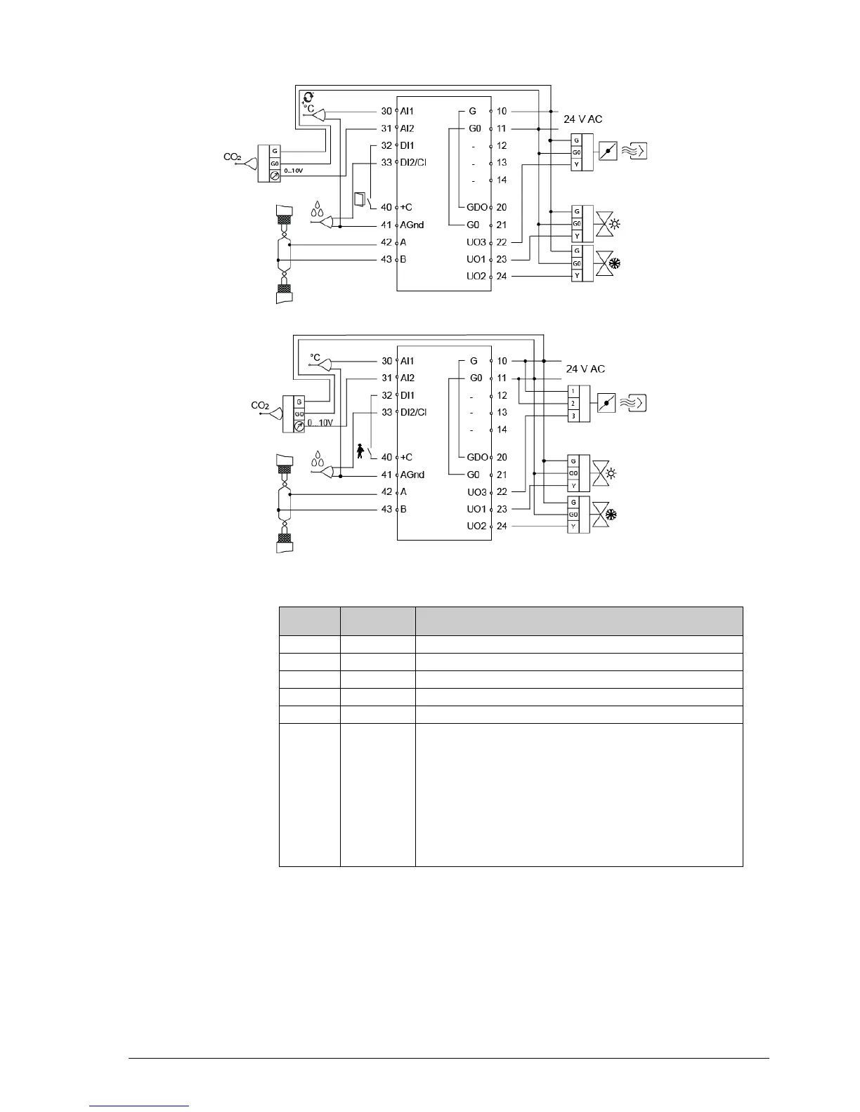
Output for VAV or EC-fan.
For forced ventilation. 24 V AC output, max. 2.0 A. 24 V actuator is
connected between terminal 22 and terminal 20, GDO.
alternatively
For 0…10 V DC damper control/EC-fan. The damper actuator/EC-fan
0…10 V control signal terminal is connected to terminal 22 and its supply
terminals to terminals 10 and 11. Make sure that the reference pole G0 is
connected to the correct terminal on the actuator.
alternatively
Lighting control On/Off.
RDAB5-24

Table of Contents

Questions and Answers:

Question and Answer IconNeed help?

Do you have a question about the Regin Regio Midi and is the answer not in the manual?

Regin Regio Midi Specifications

General IconGeneral
BrandRegin
ModelRegio Midi
CategoryController
LanguageEnglish

Related product manuals