Regio Midi manual Chapter 6 Installation 25
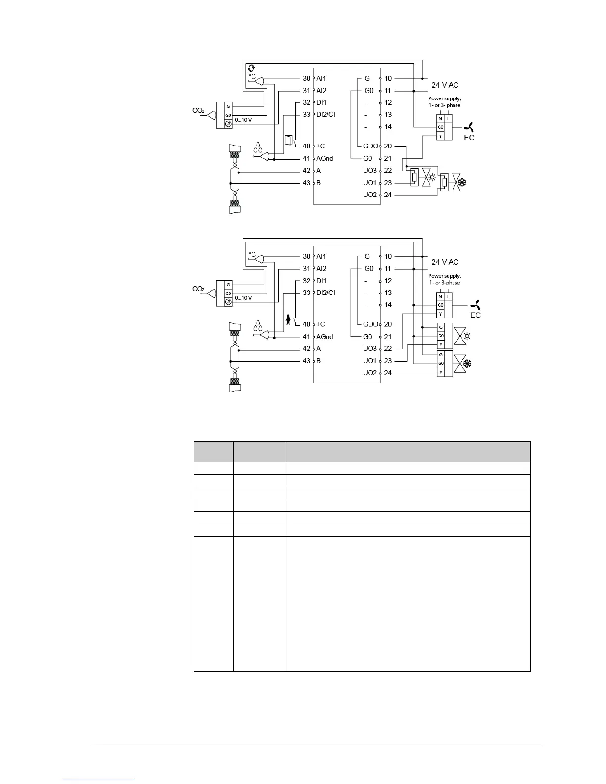
Wiring for models for CO
2
control and fan control (RC-C3DFOC)
Figure 12. Connection diagrams for models for CO
2
control and fan control
Control output heating (FS), cooling or heating or cooling via change-over.
For a 0...10 V DC valve actuator, max 5 mA (FS). The valve actuator’s 0…10
V control signal terminal is connected to terminal 23 and its supply terminals to
terminals 10 and 11. Make sure that the reference pole G0 is connected to the
correct terminal on the actuator.
alternatively
For a 24 V AC thermal actuator, max 2.0 A. The thermal actuator is connected
between terminals 23 and 20, GDO.
alternatively
For a 24V AC actuator with spring return, max. 2.0 A. The actuator is
connected between terminals 23 and 20. This can be configured either through
the display or through Regio tool
©
. The output signal for UO1 can be set to NC
(normally closed) or NO (normally open).
 Loading...